Table of Contents
Advertisement
Quick Links
Protective system control FCU 500
Furnace zone control FCU 505
Contents
1 Safety . . . . . . . . . . . . . . . . . . . . . . . . . . . . . . . . 1
2 Checking the usage . . . . . . . . . . . . . . . . . . . . . 2
3 Installation . . . . . . . . . . . . . . . . . . . . . . . . . . . . 2
control. . . . . . . . . . . . . . . . . . . . . . . . . . . . . . . . . 2
5 Cable selection. . . . . . . . . . . . . . . . . . . . . . . . . 3
6 Wiring. . . . . . . . . . . . . . . . . . . . . . . . . . . . . . . . 4
7 Connection diagram . . . . . . . . . . . . . . . . . . . . . 6
8 Adjustment. . . . . . . . . . . . . . . . . . . . . . . . . . . 12
9 Commissioning . . . . . . . . . . . . . . . . . . . . . . . 13
10 Manual mode . . . . . . . . . . . . . . . . . . . . . . . . 13
11 Assistance in the event of malfunction . . . . . 14
12 Parameters and values . . . . . . . . . . . . . . . . . 21
13 Legend . . . . . . . . . . . . . . . . . . . . . . . . . . . . . 23
14 Technical data . . . . . . . . . . . . . . . . . . . . . . . 23
15 Designed lifetime . . . . . . . . . . . . . . . . . . . . . 24
16 Logistics . . . . . . . . . . . . . . . . . . . . . . . . . . . . 24
17 Accessories . . . . . . . . . . . . . . . . . . . . . . . . . 25
18 Certification . . . . . . . . . . . . . . . . . . . . . . . . . 25
19 Disposal . . . . . . . . . . . . . . . . . . . . . . . . . . . . 26
oPeRAtInG InstRUCtIons
Cert. Version 02.19 · Edition 04.24 · EN · 03251016
1 sAFetY
1.1 Please read and keep in a safe place
Please read through these instructions
carefully before installing or operating. Following the
installation, pass the instructions on to the operator.
This unit must be installed and commissioned in
accordance with the regulations and standards in
force. These instructions can also be found at www.
docuthek.com.
1.2 explanation of symbols
1 , 2 , 3 , a , b , c = Action
➔ = Instruction
1.3 Liability
We will not be held liable for damage resulting from
non-observance of the instructions and non-com-
pliant use.
1.4 safety instructions
Information that is relevant for safety is indicated in
the instructions as follows:
DAnGeR
Indicates potentially fatal situations.
WARnInG
Indicates possible danger to life and limb.
CAUtIon
Indicates possible material damage.
All interventions may only be carried out by qualified
gas technicians. Electrical interventions may only be
carried out by qualified electricians.
1.5 Conversion, spare parts
All technical changes are prohibited. Only use OEM
spare parts.
Advertisement
Table of Contents

Related Manuals for krom schroeder FCU 505


Summary of Contents for krom schroeder FCU 505
-
Page 1: Table Of Contents
Protective system control FCU 500 Furnace zone control FCU 505 oPeRAtInG InstRUCtIons Cert. Version 02.19 · Edition 04.24 · EN · 03251016 1 sAFetY 1.1 Please read and keep in a safe place Please read through these instructions carefully before installing or operating. Following the installation, pass the instructions on to the operator. -
Page 2: Checking The Usage
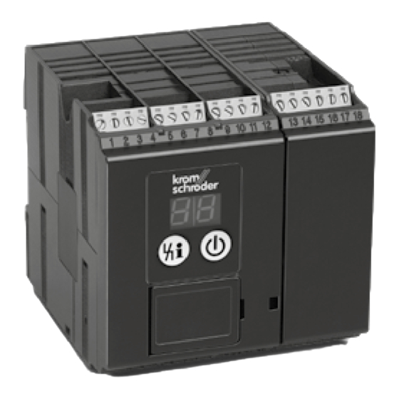
Type designation (FCU..), construction stage, input 2 CHeCKInG tHe UsAGe voltage – see type label The protective system control FCU 500 and furnace zone control FCU 505 are designed for the moni- toring and controlling of central safety functions in multiple burner systems on an industrial furnace. The FCU 500 controls multiple zones acting as the central protective system control. -
Page 3: Cable Selection
see page 12 (8 Adjustment) and page 25 (17 Accessories). 7 Slide the power module back on. 8 Mount the FCU 5xx on the DIN rail again. 9 Reconnect the connection terminals. 10 Switch the system on again, see page 13 (9 Commissioning). -
Page 4: Wiring
➔ Ensure a good PE (ground) wire connection to 6 WIRInG the burner control units and burners. ➔ Do not reverse phase L1 and neutral conduc- ➔ Ensure that a clean sinusoidal voltage is applied tor N. to the FCU so as to avoid mains voltage errors ➔... - Page 5 ➔ For burner control units or automatic burner contactors. Design the circuit as follows: control units whose safety interlock input has a current consumption of ≤ 2 mA, the power Input (max. 0.5 A, cos φ = 1) of the FCU is sufficient to Terminal 22 L1 N directly activate them.
-
Page 6: Connection Diagram
7 ConneCtIon DIAGRAM 7.1 FCU 500 ➔ Legend – see page 23 (13 Legend). × 0.6 90°➔0° 0°➔90° 3,15AT FCU 500 STM/ 0.6 x I Output L1 +24 V EN-6... - Page 7 7.2 FCU 505 ➔ Legend – see page 23 (13 Legend). × 0.6 90°➔0° 0°➔90° 3.15AT FCU 505 0.6 x I L1 +24 V EN-7...
- Page 8 ➔ Continuous control via three-point step controller. 7.3 IC 20 connected to FCU..F1 ➔ Parameter 40 = 1. 3,15AT FCU 500 12 11 3 2 1 EN-8...
- Page 9 ➔ Continuous control via analogue input. 7.4 IC 20 e connected to FCU..F1 ➔ Parameter 40 = 1. 3,15AT FCU 500 20 19 18 12 11 3 2 1 S 1 0 1 2 3 4 5 6 µC EN-9...
- Page 10 ➔ Set IC 40 to operating mode 27, see operating 7.5 IC 40 connected to FCU..F1 ➔ Parameter 40 = 2. instructions “Actuators IC 20, IC 40, IC 40S”. ➔ Continuous control via analogue input. 3.15AT FCU 500 22 21 20 19 18 16 15 14 12 11 10 EN-10...
- Page 11 7.6 RBW valve connected to FCU..F2 ➔ Parameter 40 = 3. Continuous control via three-point step controller FCU 500 R B W Continuous control via analogue input FCU 500 + F - EN-11...
-
Page 12: Adjustment
➔ Continuous control via speed-controlled fan. 7.7 Frequency converter connected to FCU..F2 ➔ Parameter 40 = 4. FCU 500 Target = actual DI 1 DI 2 DI 3 0–100% 8 ADJUstMent In certain cases, it may be necessary to change the parameters set at the factory. -
Page 13: Commissioning
➔ The display indicates H7. After pre-purge (and the 9 CoMMIssIonInG end of the valve check on FCU..C1), the valves ➔ During operation, the 7-segment display shows in the gas inlet section are opened. the program status: ➔ The display indicates 08. The FCU issues the 00 Start-up position/Standby enable signal to the burner control units to start the burners. -
Page 14: Assistance In The Event Of Malfunction
➔ Parameter 67 = 1: The FCU will terminate Man- ➔ If fault lock-out has been programmed, a fault ual mode 5 minutes after the last time the Reset/ must be acknowledged using the Reset/Informa- Information button is pressed. It switches to the tion button. - Page 15 • Ensure that the cables have been installed properly – see page 3 (5 Cable selection). • If the measures described above do not help, remove the unit and return it to the manufac- ? the display blinks and indicates 21. turer for inspection.
- Page 16 • Change the test period using parameter 57. • If the fault cannot be remedied by doing this, remove the unit and return it to the manufac- turer for inspection. ? the display blinks and indicates 40. ! The gas solenoid valve V1 is leaking. •...
- Page 17 • If the fault cannot be remedied by doing this, remove the FCU and return it to the manufac- turer for inspection. ? the display blinks and indicates 52. ! The FCU is permanently reset by remote reset. • Check remote reset activation (terminal 3). •...
- Page 18 ➔ Before the fan is switched on, there must be no High signal at the input for air monitoring (termi- nal 47) when air monitoring is activated. ? the display blinks and indicates 72. ! The connected burner control units are not ready for operation.
- Page 19 • Check the wiring. • Use interference-suppressed terminal boots • Check the gas pressure. (1 kΩ). • If the fault cannot be remedied by doing this, remove the unit and return it to the manufac- turer for inspection. ! Bus module is defective. ? the display blinks and indicates Ac.
- Page 20 Replacing the fuse • Switch on the PLC. ➔ The device fuses F1 and F2 can be removed for inspection. 1 Disconnect the system/ FCU from the electrical power supply. 2 Disconnect the connection terminals from the ? the display blinks and indicates n 1. FCU.
-
Page 21: Parameters And Values
12 PARAMeteRs AnD VALUes name ram- Value 12.1 scanning the parameters eter 1 Press the Reset/Information button for 2 s. The Air flow monitoring during post-purge display changes to parameter 10. 0 = On; maximum capacity 1 = Off; maximum capacity 2 Release the button. - Page 22 12.3 Additional parameters for FCU..H1 name ram- Value name eter ram- Value eter Minimum enable time 0–250 = Time in seconds Temperature monitoring mode 0 = Off Burner operating signal 1 = STM function (high temperature 0 = Off operation) 1 = On;...
-
Page 23: Legend
symbol Description name ram- Half of the inlet pressure Value eter A quarter of the inlet pressure Fieldbus communication Three-quarters of the inlet pressure 0 = Off 1 = On; with address check Inlet pressure 2 = On; no address check Outlet pressure Test volume 13 LeGenD... -
Page 24: Designed Lifetime
Contact rating ESD protection of terminals 5 to 8: – Control outputs LDS (terminal 16), purge Level 4 to IEC 61000-4.2 (ESD). (terminal 17), HT (terminal 18), safety interlocks Maximum deviation of temperature values of STM/ (terminal 57): STL module when using Class 1 thermocouples: max. -
Page 25: Accessories
OCU 500-2, 17 ACCessoRIes switchable display: GB, DK, S, N, TR, P, 17.1 BCsoft4 Order No. 84327031, The current software can be downloaded from our OCU 500-3, Internet site at www.docuthek.com. To do so, you switchable display: GB, USA, E, P (BR), F, need to register in the DOCUTHEK. -
Page 26: Disposal
AnsI/CsA approved American National Standards Institute/Canadian Standards Association – ANSI Z21.20/CSA C22.2, No. 199 18.2 eurasian Customs Union The products FCU 500, FCU 505 meet the technical specifications of the Eurasian Customs Union. 18.3 ReACH Regulation The device contains substances of very high con- cern which are listed in the Candidate List of the European REACH Regulation No. 1907/2006.
Need help?
Do you have a question about the FCU 505 and is the answer not in the manual?
Questions and answers