Table of Contents
Advertisement
Quick Links
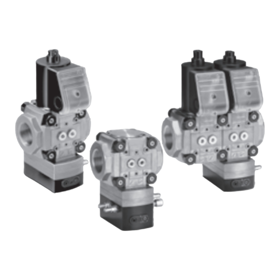
Pressure regulators with solenoid valve VAD, VAG, VAV,
VAH, flow rate regulators VRH, pressure regulators with
double solenoid valve VCD, VCG, VCV, VCH
Contents
1 Safety . . . . . . . . . . . . . . . . . . . . . . . . . . . . . . . . 1
2 Checking the usage . . . . . . . . . . . . . . . . . . . . . 2
3 Installation . . . . . . . . . . . . . . . . . . . . . . . . . . . . 3
4 Installing the gas/air control lines . . . . . . . . . . . 5
5 Wiring. . . . . . . . . . . . . . . . . . . . . . . . . . . . . . . . 7
6 Tightness test. . . . . . . . . . . . . . . . . . . . . . . . . . 8
7 Commissioning. . . . . . . . . . . . . . . . . . . . . . . . . 9
8 Replacing the actuator . . . . . . . . . . . . . . . . . . 11
9 Replacing the circuit board. . . . . . . . . . . . . . . 12
10 Maintenance. . . . . . . . . . . . . . . . . . . . . . . . . 13
11 Accessories . . . . . . . . . . . . . . . . . . . . . . . . . 13
12 Technical data . . . . . . . . . . . . . . . . . . . . . . . 17
13 Air flow rate Q. . . . . . . . . . . . . . . . . . . . . . . . 19
14 Designed lifetime . . . . . . . . . . . . . . . . . . . . . 19
15 Certification . . . . . . . . . . . . . . . . . . . . . . . . . 20
16 Logistics . . . . . . . . . . . . . . . . . . . . . . . . . . . . 21
17 Disposal . . . . . . . . . . . . . . . . . . . . . . . . . . . . 21
oPeRAtInG InstRUCtIons
Cert. Version 07.19 · Edition 03.23 · EN · 03250481
1 sAFetY
1.1 Please read and keep in a safe place
Please read through these instructions
carefully before installing or operating. Following the
installation, pass the instructions on to the operator.
This unit must be installed and commissioned in
accordance with the regulations and standards in
force. These instructions can also be found at www.
docuthek.com.
1.2 explanation of symbols
1 , 2 , 3 , a , b , c = Action
➔ = Instruction
1.3 Liability
We will not be held liable for damage resulting from
non-observance of the instructions and non-com-
pliant use.
1.4 safety instructions
Information that is relevant for safety is indicated in
the instructions as follows:
DAnGeR
Indicates potentially fatal situations.
WARnInG
Indicates possible danger to life and limb.
CAUtIon
Indicates possible material damage.
All interventions may only be carried out by qualified
gas technicians. Electrical interventions may only be
carried out by qualified electricians.
1.5 Conversion, spare parts
All technical changes are prohibited. Only use OEM
spare parts.
Advertisement
Table of Contents

Related Manuals for krom schroeder VAD


Summary of Contents for krom schroeder VAD
-
Page 1: Table Of Contents
Pressure regulators with solenoid valve VAD, VAG, VAV, VAH, flow rate regulators VRH, pressure regulators with double solenoid valve VCD, VCG, VCV, VCH oPeRAtInG InstRUCtIons Cert. Version 07.19 · Edition 03.23 · EN · 03250481 1 sAFetY 1.1 Please read and keep in a safe place Please read through these instructions carefully before installing or operating. -
Page 2: Checking The Usage
Rp internal thread Flow rate regulator with solenoid valve Flange to ISO 7005 Constant pressure governor VAD for shut-off and Quick opening, quick closing precise control of the gas supply to excess air Mains voltage 230 V AC, 50/60 Hz burners, atmospheric burners or force draught gas Mains voltage 200 V AC, 50/60 Hz... -
Page 3: Installation
VAV, VAH, CAUtIon Incorrect installation Please observe the following to ensure that the VAD, VAG, VAH: black solenoid actuator in the unit is not damaged during installation and oper- vertical upright position or tilted up to the horizontal, ation: not upside down. In humid environments: black –... - Page 4 Trans- 2.28 74924908 VAH, VRH parent If pressure regulator VAD/VAG/VAV 1 is retrofitted upstream of gas solenoid valve VAS 1, a DN 25 differential pressure orifice with outlet opening d = 30 mm (1.18") must be inserted at the outlet of the pressure regulator. To increase the control accuracy, an external In the case of pressure regulator VAx 115 or...
-
Page 5: Installing The Gas/Air Control Lines
Compression fittings 4 InstALLInG tHe GAs/AIR Con- tRoL LInes CAUtIon Incorrect installation Please observe the following to ensure that the unit is not damaged during installation and oper- ation: – Fit control lines so that no condensation can ➔ The seals in some compression fittings are enter the unit. - Page 6 Installing the air control line p and the com- bustion chamber control line p DG..C (DG..VT) min. ➔ VAV..K: 2 plastic hose couplings (internal dia. 3.9 mm (0.15"); external dia. 6.1 mm (0.24")) available. ➔ Do not remove the couplings or replace them with other types of coupling. 1 Route air control line p and combustion chamber control line p...
-
Page 7: Wiring
5 WIRInG WARnInG Risk of injury! Please observe the following to ensure that no damage occurs: LV1 N – Electric shocks can be fatal! Before working on possible live components, ensure the unit is disconnected from the power supply. – The solenoid actuator heats up during operation. -
Page 8: Tightness Test
Closed position indicator Finishing the wiring ➔ VAx open: contacts 1 and2 closed, VAx closed: contacts 1 and 3 closed. ➔ Indicator of closed position indicator: red = VAx open, white = VAx closed. ➔ Double solenoid valve: if a plug with socket is fitted, only one closed position indicator can be connected. -
Page 9: Commissioning
= 10 mbar at the setting the low-fire rate factory. ➔ If the burner operates at low-fire rate, the gas/ air mixture can be changed by adjusting the adjusting screw “N”. [mbar] ["WC] VAD..-25 2.5–25 1–10 VAD..-50 20–50 8–19.7 VAD..-100 35–100 14–40 2,5 mm 1 Switch on the burner. - Page 10 Final adjustment Presetting 6 Set the burner to low fire. 1 Set the minimum and maximum capacity on the 7 Conduct a flue gas analysis and set the gas air control valve in accordance with burner pressure at n to the desired analysis value. manufacturer’s specifications.
-
Page 11: Replacing The Actuator
8.2 Fitting the new actuator 8 RePLACInG tHe ACtUAtoR ➔ The seals of the actuator adapter set are covered ➔ The actuator adapter set for the new actuator with a non-stick coating. No additional grease is must be ordered separately. required. -
Page 12: Replacing The Circuit Board
VAx, VCx without damping unit ➔ We recommend making a note of the contact assignment for subsequent rewiring. ➔ 1 = N (–), 2 = LV1 (+) 1 Disconnect the system from the electrical power supply. 2 Close the gas supply. 7 Open the gas solenoid valve and the gas supply. -
Page 13: Maintenance
10 MAIntenAnCe 11 ACCessoRIes 11.1 Differing illustrations CAUtIon Illustrations may differ from your VAx. In order to ensure smooth operation, check the 11.2 seal set for sizes 1–3 tightness and function of the unit: When retrofitting accessories or a second valVario –... - Page 14 11.3 Pressure switch for gas DG..VC 11.4 Cable gland set The pressure switch for gas monitors the inlet pres- When wiring double solenoid valve VCx 1–3, the sure p , the interspace pressure p and the outlet connection boxes are to be connected using a pressure p cable gland set.
- Page 15 17 Connect the valves to the electrical power supply, 11.6 Bypass/pilot gas valves see section entitled “Wiring”. Prepare the installed main valve. 1 Disconnect the system from the electrical power supply. 2 Close the gas supply. ➔ Turn the actuator so that the side on which the bypass/pilot gas valve is to be installed is accessible.
- Page 16 Mounting the VBY the bypass valve’s outlet flange is designed as a 1 Grease O-rings. blind flange. ➔ For the pilot gas valve: insert sealing plug F at the outlet of the main valve if the pilot gas valve’s outlet flange is designed as a threaded flange. 4 Remove the sealing plugs on the mounting side of the bypass valve.
-
Page 17: Technical Data
Bypass valve Pilot gas valve f Wire the bypass/pilot gas valve VAS 1, see section entitled “Wiring”. g Check for tightness, see accessories, “Checking the bypass/pilot gas valve for tightness”. 11.6.3 Checking the bypass/pilot gas valve for tightness 1 To be able to check the tightness, shut off the downstream pipeline as close as possible to the 12 teCHnICAL DAtA valve. - Page 18 + max. gas pressure on burner + pressure loss Δp + 5 mbar(2 "WC). Outlet pressure p Differential air pressure Δp ) = 0.6– VAD..-25: 2.5–25 mbar (1–10 "WC), 50 mbar (0.24–19,7 "WC). VAD..-50: 20–50 mbar (8–19.7 "WC), Differential gas pressure Δp ) = 0.6– VAD..-100: 35–100 mbar (14–40 "WC).
-
Page 19: Air Flow Rate Q
Cable gland: M20 x 1.5. 13 AIR FLoW RAte Q Electrical connection: cable with max. 2.5 mm Air flow rate Q for a pressure loss of Δp = 10 mbar (AWG 12) or plug with socket to EN 175301-803. (4 "WC): Duty cycle: 100%. ∆p = 10 mbar (4 "WC) Power factor of the solenoid coil: cos φ = 0.9. -
Page 20: Certification
15.5 VAD, VAG, VAV, VAV: FM listed 15 CeRtIFICAtIon Approval does not apply for 100 V AC and 15.1 Certificate download 200 V AC. Certificates – see www.docuthek.com 15.2 Declaration of conformity Factory Mutual (FM) Research Class: 7400 and 7411 Safety overpressure slam shut valves. De- signed for applications pursuant to NFPA 85 and... -
Page 21: Logistics
16 LoGIstICs transport Protect the unit from external forces (blows, shocks, vibration). Transport temperature: see page 17 (12 Technical data). Transport is subject to the ambient conditions described. Report any transport damage on the unit or packag- ing without delay. Check that the delivery is complete. - Page 22 FoR MoRe InFoRMAtIon The Honeywell Thermal Solutions family of products includes Honeywell Combustion Safety, Eclipse, Exothermics, Hauck, Kromschröder and Maxon. To learn more about our products, visit ThermalSolutions.honeywell.com or contact your Honeywell Sales Engineer. Elster GmbH Strotheweg 1, D-49504 Lotte T +49 541 1214-0 hts.lotte@honeywell.com www.kromschroeder.com...
Need help?
Do you have a question about the VAD and is the answer not in the manual?
Questions and answers