
Related Manuals for krom schroeder E8


Summary of Contents for krom schroeder E8
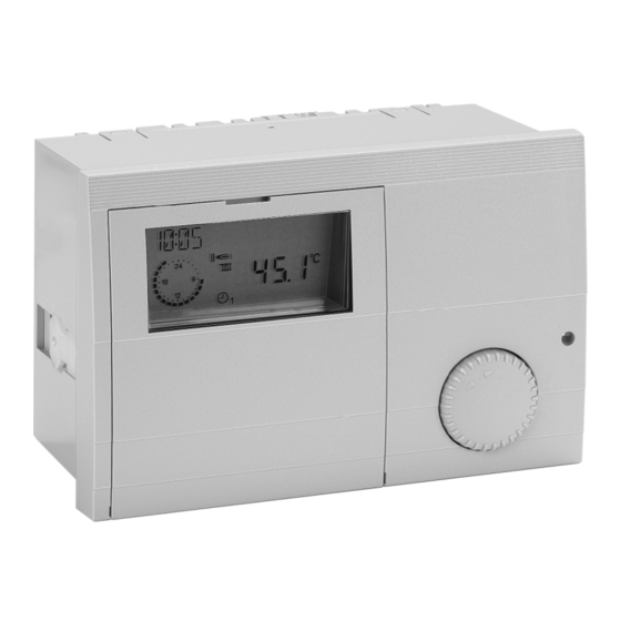
- Page 1 Operating and Heating Controller Installation Instructions Please observe the safety instructions and read through this manual carefully before commissioning the equipment.
-
Page 2: General Information
Safety information General information Warranty conditions General information Safety information If the system is not installed, commissioned, serviced and Power connection regulations repaired properly, it will render the manufacturer's warranty Please note the connection conditions specified by your null and void. local electrical power supply company and the VDE regula- Conversion tions. -
Page 3: General Notes
Automatic toggle between summer and winter time Automatic adjustment of function in accordance with the sensor configuration Declaration of conformity We the manufacturer declare the product E8.0634 is in conformity with the fundamental requirements of the follow- ing directives and standards. Directives: – 2014/35/EU, 2014/30/EU Standards: –... -
Page 4: Table Of Contents
Contents General information Expert Contents Expert HS (only for HS via eBUS) General information Levels Safety information Installation Power connection regulations Hot-water Safety Htg circuit I / II Warranty conditions Part 2: Overview of display values and settings ... - Page 5 Contents General information Hot water T-ROOM ADJ (room sensor adaptation) Heating circuit I / II OPT HEAT UP (Heating optimisation) T-DHW B (storage tank lower temperature) MAX-OPT-TIME (Maximum bring-forward) T-ROOM DES A (current value for set room OPT REDUCED (Reduction optimisation) ...
- Page 6 Contents General information Operation with two-stage heat generators or HC FUNCTION (heating circuit function selection) with 2 heat generators PUMP MODE (pump operating mode) LOCK TIME (blocking time 2. burner stage) HYST BURNER 2 (hysteresis 2. burner stage) 36 MIXER OPEN ...
- Page 7 Contents Part 4: Installation and Start-up Sensors Installation Outside sensor AF (AFS) S Assembly / Dismantling Immersion sensor KF (KFS) H/ SPF (SPFS) F 67 Connecting instructions Strap-on sensor VF (VFAS) v Notes on connecting heat generators Commissioning ...
-
Page 8: Part 1: Operation
Operation in normal mode Part 1: Operation Part 1: Operation Ç Operating mode selection Turn the knob to select the operating mode required. The operating mode selected is indicated by a symbol at the For initial start-up, please read the chapter bottom of the display. -
Page 9: Effect Of The Operating Mode
Operation in normal mode Part 1: Operation Service (automatic reset after 15 min) heat generator regulated to heat generator set temperature = max. heat generator temperature= see page 35 ; when the heat generator temperature has reached 65 °C, the consumers are regulated to their flow temperature to dissi- pate heat (cooling function). -
Page 10: Display In Normal Operation
Operation in normal mode Part 1: Operation Explanations Display in normal operation Current time Freely selectable display (refer to "DISPLAY SEL" parameter) DCF reception OK (only if receiver is connected) Bus symbol (check data lead to connected controllers if this symbol does not appear) Display of the active heating program for the first heating circuit (here: 6:00 to 08:00 hrs and 16:00 to 22:00 hrs) -
Page 11: Changing The Settings
Changing the settings Part 1: Operation Changing the settings Operating elements Ç A => Shaft encoder The operating flap must be opened first in order to change Search for value/level or adjust value or request set values. Ä => Controller switches to Operation mode B =>... -
Page 12: Operating Level
Changing the settings Part 1: Operation Operating level Operation is divided into different areas: General - Display - Users - Time Programs - Expert - General SERVICE Expert HS DATE/TIME/HOLIDAY Opening the hinged control panel cover automatically Open Ç Turn anticlocwise takes you to the display and indicator area. -
Page 13: Areas
Changing the settings Part 1: Operation Areas Levels The settings in the different areas are sorted into operating General levels Value selection summary INSTALLATION Service => for service engineers HOT WATER Date/Time/Holiday => for users HEAT CIRCUIT I Display ... -
Page 14: Part 2: Overview Of Display Values And Settings
General area Part 2: Overview of display values and settings Part 2: Overview of display values and settings Part 2: Overview of display values and set- Ç Hinged cover OPEN search for level to the left with tings Ä open with General area If a heating system controller has been set to be the... - Page 15 General area Part 2: Overview of display values and settings Please do not enter the day of travel as the start Holiday => Value group date, but the first day of the holiday (no more (General -> Date/Time/Holiday level) heating from this day). All the values in this level are set in sequence =>...
-
Page 16: Service
General area Part 2: Overview of display values and settings Service ~ Hinged cover OPEN search for level to the left with Ç, This area contains values for the customer service engi- open with Ä neers in order to provide rapid access. A code number must be entered for this function. -
Page 17: Sensor Test
General area Part 2: Overview of display values and settings SENSOR TEST Sensor test => Value group (General -> Service level) Multifunction sensor according to function set for relay Select sensor using Ç => value is displayed 01 = Header pump T-OUTSIDE Outside temperature =>... -
Page 18: Sw No Xxx-Xx
General area Part 2: Overview of display values and settings Other entries SW NO XXX-XX (General -> Service level) Display software number with index (please specify if you Select value using Ç => value is displayed experience problems or have questions about the control- ler) SW NO XXX-XX Software number with index... -
Page 19: Service
General area Part 2: Overview of display values and settings SERVICE Input of values for the yearly maintenance message Delete active maintenance display: Open control panel cover, press prog. button 2x Ä, set display value to "00" using Ç and confirm with Ä. Delete programmed yearly message: At the level General/Service set the value SERVICE =>DAY or... -
Page 20: Display Range
Display Range Part 2: Overview of display values and settings Display Range T-OUTSIDE The measured outside temperature is smoothed for control Display only. No adjustments possible. Display only purposes. The smoothed value is displayed here. appears if the sensor is connected and the value is present in the system. -
Page 21: T-Buffer B
Display Range Part 2: Overview of display values and settings T-CIRCL = Return temperature of the circulation pipe CIRCL PULSE = for circulation pump via pulse the pulse input status is displayed (ON/OFF) T-DHW B = Temperature of hot water storage tank at inlet area HTG CIRCUIT3 = for additional direct heating circuit the pulse input status is displayed (ON/OFF) -
Page 22: Heating Circuit I / Ii
Display Range Part 2: Overview of display values and settings Display only appears if the sensor is connected and Hot water the value is present in the system. T-DHW DES Current hot water set tempera- If the set value is not present it is masked out, or ture according to heating pro- hyphens appear in the display (- - - -). -
Page 23: User Area
User Area Part 2: Overview of display values and settings User Area Ç ~ Hinged cover OPEN search for level to the right with Ä open with All the settings that can be made by the operator of the system. -
Page 24: Hot Water
User Area Part 2: Overview of display values and settings Charging starts when the temperature drops below set Hot water temperature " T-DHW 1 DES " by the switching hysteresis. After charging, the value is automatically set to "00". Designation Value range Default T-DHW 1 - 3 DES (Hot water temperature setting) -
Page 25: Heating Circuit I / Ii
User Area Part 2: Overview of display values and settings *) depending on function selector Heating circuit T-POOL, Heating circuit I / II T-DHW, T-FLOW DAY or T-FLOW REDUC (see page 46) Designation Value range Default MODE MODE ----, ,F1,F2,B,B - - - - - - - - =>... -
Page 26: T-Limit Day/T-Limit N (Day/Night)
User Area Part 2: Overview of display values and settings T-LIMIT DAY/T-LIMIT N (Day/Night) Flow temperature [°C] Only valid if the function is activated => Set value "Expert/Heating circuit/PUMP MODE= 01=> Pump switch- ing according to heating limit" If the outside temperature that is measured and calculated by the controller exceeds the heating limit specified here by 1 K (= 1 °C), heating is disabled, the pumps switch off and the mixers are closed. -
Page 27: Adaption (Heat Slope Adaption)
User Area Part 2: Overview of display values and settings Guideline values During the adaptation, the water heating and the heating optimisation of the regulator are blocked. Underfloor heating S = 0.4 to 0.6 Radiator heating S = 1.0 to 1.5 ROOM INFL (Room sensor influence) Only active if an FBR analogue room device is connected ADAPTION (heat slope adaption) -
Page 28: Opt Heat Up (Heating Optimisation)
User Area Part 2: Overview of display values and settings OPT HEAT UP (Heating optimisation) MAX-OPT-TIME (Maximum bring-forward) Activation of function for automatically bringing forward the Only active with " OPT HEAT UP = 01 or 02" start of heating. The start of heating is brought forward by no more than this time. -
Page 29: Timer Program Area
Timer Program Area Part 2: Overview of display values and settings Timer Program Area Ç ~ Hinged cover OPEN search for level to the right with Ä open with All the time programs can be set in this area. Selecting a timer program List of available time programs With maximum controller configuration... -
Page 30: Timer/Heating Program Adjustment
Timer Program Area Part 2: Overview of display values and settings Timer/heating program adjustment Ç Select weekday (Mo-Su) or block (MO - FR => Monday-Friday, SA - SU => Saturday- Sunday, MO - SU => Monday-Sunday) Ä Open weekday/block (see left) =>... - Page 31 Timer Program Area Part 2: Overview of display values and settings Heat circuit 1 Heat circuit 2 Heating program 1 => factory setting: Heating program 1 => factory setting: Mo. to Fr.: 06:00 to 22:00 Mo. to Fr.: 06:00 to 22:00 Sa.
- Page 32 Timer Program Area Part 2: Overview of display values and settings Hot water Circulation Factory setting: Factory setting: Mo. to Fr.: 05:00 to 21:00 Mo. to Fr.: 05:00 to 21:00 Sa. and So.: 06:00 to 22:00 Sa. and So.: 06:00 to 22:00 ...
-
Page 33: Expert Area
Expert area Part 2: Overview of display values and settings Expert area *) only for HS via eBUS These settings can only be changed if the code no. is en- 1) Controller .0324-P and .0634-P = 67 °C tered (see page 16). 2) Controller .0324-P and .0634-P = 62 °C 3) Controller .0324-P and .0634-P = 01 E If these values are set incorrectly, they may cause... -
Page 34: Bus Termin
Expert area Part 2: Overview of display values and settings BUS TERMIN No more than 1 TIME MASTER is permitted in the system! This parameter is used to switch the terminal resistance for Can communication. The entire system may contain exact- DYN UPWARD (dyn. -
Page 35: Max T-Hs
Expert area Part 2: Overview of display values and settings Small values cause a fast regulatory behavior and 00 = Minimum limit on heat slope could cause to a oscillation of the boiler The heat generator switches on when the temperature. -
Page 36: Hysteresis (Dynamic Switching Hysteresis)
Expert area Part 2: Overview of display values and settings er HYSTERESIS setting takes effect. Short run-times and Installation frequent burner operation are prevented. Designation Value range Default High heat consumption HYSTERESIS 5 K – 20 K During longer periods of burner operation (high heating load) the hysteresis is automatically reduced to 5 K. -
Page 37: Sequence Change(Time For Switching Hs)
Expert area Part 2: Overview of display values and settings - and temperature drops below temperature setting by 5 K Stage 1 on Start of blocking time (= start of blocking time / enable 2nd. burner stage) Stage 2 on (stage 2 enable) - and expiration of blocking time Stage 2 off Switch off 2nd burner stage when the temperature setting... -
Page 38: Auxiliary Relay Functions
Expert area Part 2: Overview of display values and settings 00 = no function Installation 01 = Header pump Designation Value range Default ON: When heat is requested by a consumer FUNC RELAY 1 00 – 32 OFF: Without consumer heat request If at least one consumer in the system requests heat the T-MF1 30 °C –... - Page 39 Expert area Part 2: Overview of display values and settings 20 = Temperature-controlled circulation pump T-SOLID FUEL > [T-BUFFER B + HYST MF 1 + 5K] T-CIRCL = Return flow temperature of circulation line OFF: T-SOLID FUEL < T-CIRCL < T-MF1 [T-BUFFER B + HYST MF 1] OFF: T-CIRCL >...
-
Page 40: Func Relay 2 (Function Selection Relay 2)
Expert area Part 2: Overview of display values and settings Disabling the HS1 only occurs if the solid fuel boiler 24 = return flow temperature increase is integrated in the HS1 controller. T-RETURN = Return temperature of system If the cooling function is activated, it will also affect RETURN TEMP <... - Page 41 Expert area Part 2: Overview of display values and settings 03 = Booster pump ON: In the event of a heating request from an internal con- sumer OFF: Without internal consumer heating request A pump after-run occurs. 05 = Pump heat generator 1 When using the controller to control two heat generators the relay may be used to control the heat generator pump for heat generator 1.
-
Page 42: Screed Program
Expert area Part 2: Overview of display values and settings Screed program Installation SCREED (activation of screed drying process) Designation Value range Default The screed program can be used for function heating in SCREED 00, 01 (OFF/ON) 00 = OFF accordance and for heating freshly laid screed ready for flooring. -
Page 43: Hot Water
Expert area Part 2: Overview of display values and settings PARALLEL DHW (Pump parallel running) Hot water *) Function with [CoCo2 index03] => 02 = 03; Designation Value range Default with CoCo1/CoCo2 (< index 03) => 01 = 00 and 02 = 03 DHW RELIEF 00, 01 (OFF/ON) 01 = ON 00 =>... -
Page 44: During Hot Water Preparation)
Expert area Part 2: Overview of display values and settings pump has already been switched on again when the heat DHW FOLLOWUP (pump run-down time) generator temperature drops below the temperature [max- 00 min => Standard function: The charging pump contin- imum flow temperature + 5 K]. -
Page 45: Load Through
Expert area Part 2: Overview of display values and settings LOAD THROUGH T-DHW = Temperature of hot water storage tank at outlet area Storage tank charging: T-DHW < T-DHW DES - HYST DHW OFF T-DHW B > T-DHW DES Charging the storage tank is stopped when the storage tank set temperature is measured at the lower sensor. -
Page 46: Heating Circuit I / Ii
Expert area Part 2: Overview of display values and settings [T-FLOW DAY], and during reduced mode operation with a The parameters in this level change in accordance with the fixed preset flow temperature [T-FLOW REDUC] accord- heating circuit function that has been selected ingly. -
Page 47: Pump Mode (Pump Operating Mode)
Expert area Part 2: Overview of display values and settings The heat generator controller's hot water priority function 00 => Standard circulation pump control can be used. Heating time: Outside temperature > room set value + 1 K If an optional storage tank flow temperature sensor Reduction time: and lower storage tank sensor is connected, the ROOM INFL =0:... -
Page 48: Mixer Open
Expert area Part 2: Overview of display values and settings MIXER OPEN (mixer dynamics when opening) 1) Controller .0324-P and .0634-P = 35 K Speed setting at which the mixer motor opens when a con- trol difference occurs. The control difference at which the MAX T-FLOW(maximum flow temperature) mixer motor opens without interruption is entered in Kelvin. -
Page 49: T-Out Delay (Outside Temperature Delay)
Expert area Part 2: Overview of display values and settings T-OUT DELAY (outside temperature delay) The selected outside temperature delay must be matched to the type of construction of the building. In the case of heavy structures (thick walls), a long delay must be select- ed since a change in outside temperature affects the room temperature later accordingly. -
Page 50: Part 3: General Function Description
Expert area Part 3: General function description Part 3: General function description Hot water generation Part 3: General function description The programmed hot water temperature is stabilised by Heat circuit control switching the hot-water cylinder charging pump and the burner. Storage tank charging starts when the storage tank Weather-dependent control temperature drops below the temperature setting by 5 K. -
Page 51: Ebus Burner Controls
Expert area Part 3: General function description Heat generator frost protection eBUS burner controls The controller supports the operation of burner controls via The heat generator frost protection is activated when the the implemented eBUS. The unit is connected by means of heat generator temperature drops below 5 °C. -
Page 52: Eeprom Check
Expert area Part 3: General function description If the room temperature factor is "0", the pump EEPROM check continues to run during the reduced operation period Every 10 minutes, a check is conducted automatically in after a one-off heating demand. order to establish whether the settings of the controller lie within the specified limits. -
Page 53: Part 4: Installation And Start-Up
Installation Part 4: Installation and Start-up Part 4: Installation and Start-up Installing the controller: Part 4: Installation and Start-up 1. Set the mounting clamp to the wall thickness of the con- Installation trol panel (at the left and right-hand side of the unit): Assembly / Dismantling a. -
Page 54: Connecting Instructions
Installation Part 4: Installation and Start-up e. Lever the tool with respect to the unit exterior wall. Connecting instructions This causes the mounting clamp to release the control E The controller is designed for an operating current of panel wall. AC 230 V at 50 Hz. - Page 55 Installation Part 4: Installation and Start-up Note for installation in connection with digital room device When installing a digital room device, the heating circuit- specific set values are adjusted at the room device. These values are automatically faded out inside the controller. If during operation the digital room device is separated from the BUS for a longer time period (>...
-
Page 56: System Diagram
Installation Part 4: Installation and Start-up System diagram Depending on controller type, only partial functions Maximum configuration: are assigned for your controller. HS regulation (2-stage) Hot water generation 2 mixed heating circuits, remote-controlled via BUS or 1 mixed heating circuit & Fixed value / Pool regulation Return increase/Solar/Solid fuel Circulation pump... -
Page 57: System Diagram With Hs Via Ebus
Installation Part 4: Installation and Start-up System diagram with HS via eBUS Depending on controller type, only partial functions Maximum configuration: are assigned for your controller. HS regulation modulating Hot water generation 2 mixed heating circuits, remote-controlled via BUS or 1 mixed heating circuit &... -
Page 58: Electrical Connection
Installation Part 4: Installation and Start-up Electrical connection Terminal wiring Version 1 VII (1 + 2): eBUS (HS) or eBUS - DCF (1 - 3): FBR2 (FBR1) for heating circuit 1 ~230 V; Relay switching capacity 2(2) A, ~250 V (4 + 5): Flow sensor, heating circuit 2 (6 + 7): Storage tank sensor (7 + 8): Boiler sensor... - Page 59 Installation Part 4: Installation and Start-up Version 2 Terminal wiring ~230 V; Relay switching capacity 2(2) A, ~250 V (1 + 2): eBUS (HS) or eBUS - DCF (1 - 3): FBR2 (FBR1) direct heating circuit (4 + 5): Flow sensor mixer circuit (6 + 7): Storage tank sensor (7 + 8): Boiler sensor (9 + 10): Outdoor sensor...
-
Page 60: Power Terminal Assignments
Installation Part 4: Installation and Start-up Power terminal assignments Plug 2 [II] Neutral conductor, mains Options Power supply, unit Provided no separate L1´: Power supply to relay regulations for protecting 1: heating circuit pump HK 1 the relay apply, a bridge 2: heating circuit pump HK 2 to supply the relay must Storage tank charging pump... -
Page 61: Sensor Terminal Assignments
Installation Part 4: Installation and Start-up Sensor terminal assignments Connector 7 [VII] with eBUS Pin 1: eBUS (HS) or eBUS - DCF Pin 2: eBUS (ground) Connector 1 [I] for HC as HW circuit Pin 1: Storage tank sensor flow Pin 2: (ground) Pin 3: Storage tank sensor lower Connector 1 [I]... - Page 62 Installation Part 4: Installation and Start-up Connector 5 [V] Pin 1: Flow sensor, heating circuit 1 (ground) Pin 2: Flow sensor, heating circuit 1 Connector 8 [ VIII ] Pin 1: Sensor, multifunction relay 1 (ground) Pin 2: Sensor multifunction relay 1 Connector 3 [III] (without solar integration) Pin 1: FBR heating circuit 2 (room sensor) Pin 2: FBR heating circuit 2 (ground)
-
Page 63: Remote Controls
Remote controls Part 4: Installation and Start-up Remote controls Remote control FBR2 Electrical connection: Connector I; 1 - 3 and The operator module Merlin BM, BM 8, Lago FB connector III; 1 - 3 (Only for controller models with CAN-Bus connection) Electrical connection: Connector IX;... -
Page 64: Sensor Resistances Fbr
Remote controls Part 4: Installation and Start-up Installation location: DCF receiver Electrical connection: Connector VII; 1, 2 In reference / main living room of the heating circuit The controller can evaluate a eBUS DCF receiver on the (on an inside wall of the room). eBUS FA-Terminals. -
Page 65: Maximum Delimiter
Remote controls Part 4: Installation and Start-up Maximum delimiter Telephone switch If a maximum delimiter is required it must be connected between the heating circuit pump and the pump controller switch output. Connector I, terminals 4 and 5 The heating system can be switched to Heating mode with a telephone switch. -
Page 66: Sensor Values / Characteristic Curve
Remote controls Part 4: Installation and Start-up Sensor values / characteristic curve 5 kOhm NTC: AF, KF, SPF, VF Temperature 5 kOhm NTC 1 kOhm PTC -60 °C 1 kOhm PTC: AFS, KFS, SPFS, VFAS 698961 -50 °C 333908 ... -
Page 67: Sensors
Sensors Part 4: Installation and Start-up Sensors Strap-on sensor VF (VFAS) v Outside sensor AF (AFS) S Order no. VF, 5 kΩ, 3 m, ø 6.0x50: 99 679 073 Order no. AF, 5 kΩ: 99 679 030 Order no. VFAS, 1 kΩ, 3 m, ø 6.0x50: 99 679 051 Order no. -
Page 68: Commissioning
Commissioning Part 4: Installation and Start-up Commissioning Commissioning procedure 1. Please read this guide carefully before commissioning Commissioning level 2. Fit controller, make electrical connections and switch All the values in this level must be entered in sequence on heat generator and supply voltage without interruption 3. -
Page 69: System Bus
System bus Part 4: Installation and Start-up System bus Bus ID For mixer motor controllers and control units The heating system The bus ID (00 - 15; expert level parameter) is used to This controller can be expanded in a modular fashion us- number the heating circuits in the system. -
Page 70: Error Messages
System bus Part 4: Installation and Start-up Error messages Error no. Error description Communication error E 90 ID 0 and 1 on bus. Bus IDs 0 and 1 may not be If a fault or error occurs in the heating system, you will see used simultaneously. -
Page 71: Troubleshooting
Troubleshooting Part 4: Installation and Start-up In mixer motor expansion controllers with connection to Troubleshooting Boiler controller => Display of the outside temperature and the heat generator temperatire General (see " Display/Installation“) If your system malfunctions you should first check that the Control unit =>... - Page 72 Troubleshooting Part 4: Installation and Start-up Burner does not switch of at correct time Check minimum heat generator temperature and type of minimum delimiter => Protect from corrosion Burner will not switch on Check set temperature of heat generator => The set tem- perature must be above the current heat generator tem- perature.
-
Page 73: Dimensions
Dimensions Dimensions... -
Page 74: Technical Data
Technical data Technical data AC 230 V 10 % Supply voltage in acc. with Increase in Control Combined with EN 60038 efficiency* class Power consumption max 8 W Outdoor temperature control Switching capacity of the relays AC 250 V 2(2) A Room temperature control Maximum current on 10 A... -
Page 75: Glossary
Glossary Return flow booster Glossary The return flow booster prevents the temperature differ- ence at the heat source between flow an return becoming Flow and return flow temperature too great. A mixing valve is here used to add a portion of The flow temperature is the temperature to which the heat the hot flow water to the return flow. - Page 76 Glossary Header pump A header pump is used to pump the hot water in a system Malfunctions due to improper operation or settings are not cov- with one or several heat sources. It is switched on as soon ered by the warranty. as a consumer in the system requests heat.
Need help?
Do you have a question about the E8 and is the answer not in the manual?
Questions and answers