Table of Contents
Advertisement
Quick Links
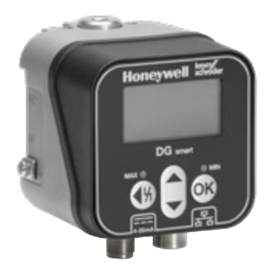
Gas pressure sensor DG smart
Contents
1 Safety . . . . . . . . . . . . . . . . . . . . . . . . . . . . . . . . 1
2 Checking the usage . . . . . . . . . . . . . . . . . . . . . 2
3 Installation . . . . . . . . . . . . . . . . . . . . . . . . . . . . 2
4 Electrical connection. . . . . . . . . . . . . . . . . . . . . 3
5 User keys and display . . . . . . . . . . . . . . . . . . . 4
6 LEDs (colour/flash code) . . . . . . . . . . . . . . . . . 4
7 Operation . . . . . . . . . . . . . . . . . . . . . . . . . . . . . 5
8 Parameter . . . . . . . . . . . . . . . . . . . . . . . . . . . . 5
9 Settings . . . . . . . . . . . . . . . . . . . . . . . . . . . . . . 7
10 Statistics. . . . . . . . . . . . . . . . . . . . . . . . . . . . . 8
11 Information . . . . . . . . . . . . . . . . . . . . . . . . . . . 9
12 Service . . . . . . . . . . . . . . . . . . . . . . . . . . . . . . 9
13 Changing the password . . . . . . . . . . . . . . . . . 9
14 Commissioning. . . . . . . . . . . . . . . . . . . . . . . . 9
15 Tightness test . . . . . . . . . . . . . . . . . . . . . . . . 10
16 Checking the function. . . . . . . . . . . . . . . . . . 10
17 Accessories . . . . . . . . . . . . . . . . . . . . . . . . . 10
18 Maintenance. . . . . . . . . . . . . . . . . . . . . . . . . 10
19 Assistance in the event of malfunction . . . . . 11
20 Technical data . . . . . . . . . . . . . . . . . . . . . . . 12
21 Designed lifetime . . . . . . . . . . . . . . . . . . . . . 14
22 Certification . . . . . . . . . . . . . . . . . . . . . . . . . 14
23 Logistics. . . . . . . . . . . . . . . . . . . . . . . . . . . . 14
24 Disposal . . . . . . . . . . . . . . . . . . . . . . . . . . . . 15
oPeRAtInG InstRUCtIons
· Edition 03.23 · EN · 03251643
1 sAFetY
1.1 Please read and keep in a safe place
Please read through these instructions
carefully before installing or operating. Following the
installation, pass the instructions on to the operator.
This unit must be installed and commissioned in
accordance with the regulations and standards in
force. These instructions can also be found at www.
docuthek.com.
1.2 explanation of symbols
1 , 2 , 3 , a , b , c = Action
➔ = Instruction
1.3 Liability
We will not be held liable for damage resulting from
non-observance of the instructions and non-com-
pliant use.
1.4 safety instructions
Information that is relevant for safety is indicated in
the instructions as follows:
DAnGeR
Indicates potentially fatal situations.
WARnInG
Indicates possible danger to life and limb.
CAUtIon
Indicates possible material damage.
All interventions may only be carried out by qualified
gas technicians. Electrical interventions may only be
carried out by qualified electricians.
1.5 Conversion, spare parts
All technical changes are prohibited. Only use OEM
spare parts.
Advertisement
Table of Contents

Related Manuals for krom schroeder DG smart


Summary of Contents for krom schroeder DG smart
-
Page 1: Table Of Contents
Gas pressure sensor DG smart oPeRAtInG InstRUCtIons · Edition 03.23 · EN · 03251643 1 sAFetY 1.1 Please read and keep in a safe place Please read through these instructions carefully before installing or operating. Following the installation, pass the instructions on to the operator. -
Page 2: Checking The Usage
2.3 type label 2 CHeCKInG tHe UsAGe Gas type, switching pressure, max. inlet pressure, For monitoring positive or differential pressures of ambient temperature, mains voltage and output gas, air, flue gas or other non-aggressive gases. signals: see type label. This function is only guaranteed when used within the specified limits –... -
Page 3: Electrical Connection
3.3 Connections 4 eLeCtRICAL ConneCtIon 1 or 2 for positive 1 Note the recommended tightening torques. See pressure Rp ¼ ( ¼" NPT) page 13 (20.2.1 Recommended tightening torque). 3 Breather orifice Voltage supply and 4–20 mA signal 2 Disconnect the system from the electrical power Relative pressure (positive pressure) supply. -
Page 4: User Keys And Display
5 UseR KeYs AnD DIsPLAY 6 LeDs (CoLoUR/FLAsH CoDe) Two changing colour LEDs show the status of the MAX/MIN function or a message. ➔ If the MAX/MIN function is disabled, the LEDs remain off during normal operation. Colour and flash code ➔... -
Page 5: Operation
(5 Hz) may be active) 50.0 mbar Perma- Alarm Internal device error nent DG smart Eth:con Limit ½: 20.0/60.0 mA:12 Overpressure has been detected and For details of the Modbus TCP, see TI DGS, section Overpres- Flash- the pressure is now entitled “Modbus Holding Register”. - Page 6 8.2 safety parameters All safety parameters are password-protected. The user must be logged in to edit them. Factory default name translation Value range settings Transmitter page 6 (8.2.1 Sensor function) Sensor function Transmitter MAX and MIN function MAX switching page 6 (8.2.2 MAX switching value) Setting 0 mbar value...
-
Page 7: Settings
8.3 non-safety parameters Factory default name translation Value range settings page 7 (8.3.1 MAX warning) MAX warning Setting 0 mbar page 7 (8.3.2 MAX alarm) MAX alarm Setting 0 mbar page 7 (8.3.3 MIN warning) MIN warning Setting 0 mbar page 7 (8.3.4 MIN alarm) MIN alarm Setting 0 mbar... -
Page 8: Statistics
9.1 Measuring unit 9.2 temperature unit Display settings Value range Description Measuring unit mbar Celsius is displayed. Decimal separator Brightness 100% Fahrenheit is displayed. Temperature Kelvin is displayed. Value range Description 9.3 Decimal separator mbar mbar is displayed. Display: “.” or “,” as the decimal separator. kPa is displayed. -
Page 9: Information
The Service section can only be accessed via the process. web server. See TI DG smart, section entitled “Web 1 Vent the gas pipe. server”. 2 Read the pressure value and enter it in Parame- 12.2 Resetting event history/customer statis-... -
Page 10: Tightness Test
45 (1.77") differential pressure measurement. 25 (0.98") 17 ACCessoRIes 17.1 test key PIA To test the min. pressure switch, the DG SMART can be vented in its switched state using the PIA test key (contains non-ferrous metals). 24 (0.94") (1.69") -0,3 64 (2.52") -
Page 11: Assistance In The Event Of Malfunction
? Mains voltage? The Service parameter can only be accessed via the ! The function for reading the mains voltage is web server. See TI DG smart, section entitled “Web defective. server”. • Reset the unit once. -
Page 12: Technical Data
? MAX pressure? • If the measure described above does not help, remove the unit and return it to the manufac- ! The pressure has exceeded the set MAX switch- turer for inspection. ing pressure. 19.1 Resetting • Ensure that the inlet pressure is within the ➔... - Page 13 20.3.1 output signal coding Upper housing section: steel fibre reinforced PBT plastic with low gas release. The 4–20 mA output supplies the current pressure in Lower housing section: AlSi 12. the form of an analog value. The pressure measur- Rp 1/4 (1/4" NPT) connecting thread. ing range is scaled to 4–20 mA.
-
Page 14: Designed Lifetime
Transport is subject to the ambient conditions We, the manufacturer, hereby declare that the prod- described. uct DG SMART with product ID No. CE-(Data still Report any transport damage on the unit or packag- missing -> in progress) complies with the require- ing without delay. -
Page 15: Disposal
24 DIsPosAL Devices with electronic components: Weee Directive 2012/19/eU – Waste electrical and electronic equipment Directive At the end of the product life (number of operat- ing cycles reached), dispose of the packaging and product in a corresponding recycling centre. Do not dispose of the unit with the usual domestic refuse. - Page 16 FoR MoRe InFoRMAtIon The Honeywell Thermal Solutions family of products includes Honeywell Combustion Safety, Eclipse, Exothermics, Hauck, Kromschröder and Maxon. To learn more about our products, visit ThermalSolutions.honeywell.com or contact your Honeywell Sales Engineer. Elster GmbH Strotheweg 1, D-49504 Lotte T +49 541 1214-0 hts.lotte@honeywell.com www.kromschroeder.com...
Need help?
Do you have a question about the DG smart and is the answer not in the manual?
Questions and answers