Table of Contents
Advertisement
Advertisement
Table of Contents

Related Manuals for Sennheiser SR 3254


Summary of Contents for Sennheiser SR 3254
- Page 1 SR 3254 SR 3256 Instructions for use SR 3254 SR 3256...
-
Page 2: Table Of Contents
The operating menu of the transmitter ........19 Overview of the operating menu ............20 Selecting the frequencies to be stored in the channel bank “U” ...21 Selecting a channel from the channel bank “U” or “F” ....22 Switching between mono and stereo operation ........22 Care and maintenance ..............23... -
Page 3: Safety Instructions
Follow all instructions. Operation Use the device in dry rooms only. To reduce the risk of fire or electric shock, do not expose the device to rain or moisture. Objects filled with liquids, such as vases or coffee cups, must not be placed on the device. - Page 4 This device should be operated only from the type of power source indicated on the marking label. lf you are not sure of the type of power supply to your building, consult your dealer or local power company.
- Page 5 The adjoining adhesive label is attached to the devices back. The symbols on this label have the following meaning: This symbol is intended to alert the user to the presence of un- insulated dangerous voltage within the product's enclosure that may be of sufficient magnitude to constitute risk of fire or electric shock.
- Page 6 Improper use Improper use is when you use the transmitter other than described in these instructions or when you use the transmitter under operating conditions different from those described in these instructions.
-
Page 7: Sr 3254/Sr 3256 Transmitters
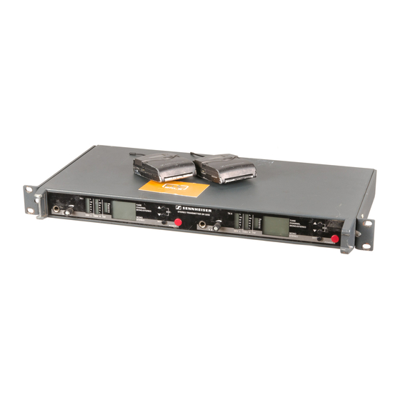
Sennheiser’s noise reduction system. The SR 3254 is a single stereo transmitter in a 19" 1 U housing. SR 3254 The SR 3256 consists of two complete stereo transmitters in a 19"... -
Page 8: Delivery Includes
The channels of the channel bank “F“ (fixed bank) have been factory-preset to customer-specific transmission frequencies. These frequencies cannot be changed. The channel bank “U” (user bank) allows you to freely select and store frequencies. Recommended receiver EK 3253... -
Page 9: Overview Of Operating Controls
Type plate Alphanumeric LC display Antenna output button button (UP) button (DOWN) POWER button Note: Connections and operating controls marked with a star ( ) in the above illustration are those for the second transmitter of the SR 3256 twin transmitter. -
Page 10: Indications And Displays
(two separate bargraphs for the left and right channel) Deviation display The two bargraphs indicate the deviation of the audio signal of the left and right channel. When the transmitter’s audio input level is excessively high, “PEAK” lights up. Display of the RF output power The bargraph indicates the RF output power. -
Page 11: Preparing The Transmitter For Use
Ensure that the base of the transmitter is clean and free from grease before mounting the rubber feet. Fix the rubber feet to the base of the transmitter by peeling of the safety paper and fitting them as shown in the diagram on the left. -
Page 12: Rack-Mounting Several Transmitters
Rack-mounting several transmitters You can use the supplied rack mount “ears” to mount the transmitter into a 19" rack (1 U). If you wish to mount the antennas to the front of the rack, use the GA 3030-AM antenna mount (see “Accessories” on page 29). - Page 13 We recommend not stacking more than two transmitter directly one above the other, and then providing for a duct of sufficient size to ensure a free air flow between the transmitters. Rack-mounting the transmitter without mounting the antennas to the front of the rack Hook the two rack mount “ears”...
- Page 14 Pull the cables of the antenna holders through the holes in the rack mount “ears”. Secure the rack mount “ears” to the left and right of the transmitter using four recessed head screws respectively. Connect the cables of the antenna holders to the antenna sockets at the rear of the transmitter.
-
Page 15: Connecting The Transmitter To The Mains
Connecting the transmitter to the mains The transmitter can be connected to 230 V or 115 V AC. Before you plug the mains connector into the wall socket, please first check that the transmitter is set to the correct mains voltage! -
Page 16: Using Transmitters In A Multi-Channel System
To do so, you require an antenna combiner (e.g. the AC 3000, see “Accessories” on page 29) which allows you to combine the signals of up to four twin receivers onto a single antenna (see diagram below). For detailed information on... - Page 17 Use a low-attenuation 50-Ω cable to connect the antenna to the transmitter. Ready-made antenna cables from Sennheiser are available as accessories with length of 5 m and 10 m. If possible, use a short antenna cable and as little connections as...
-
Page 18: Using The Transmitter
After switch-on, the LC display is backlit and the last transmission frequency set is displayed. Until the PLL has locked on the desired transmission frequency, the transmitter is muted. “MUTE” appears on the display and the LCD bargraph for RF output power (RF) indicates 0 %. - Page 19 Even during mono operation, the left and right channel are reproduced separately via the headphones. First, set the volume control to the lowest volume by turning it to the left as far as possible. Then gradually turn up the volume.
-
Page 20: The Operating Menu Of The Transmitter
The operating menu of the transmitter Via the operating menu, you can quickly and easily change the following settings: Menu Function of the menu TUNE Setting a transmission frequency for the channel bank “U” (user bank) CHANNEL Selecting a channel from the channel bank “U” or “F”... -
Page 21: Overview Of The Operating Menu
Overview of the operating menu Display mode Setting mode Press SET for 1 sec. : U 1... U 16, F 1... F16 Current channel SET: Selects the channel : Transmission Current frequency frequency in steps of 5 kHz Current channel or current Changing the channel : U 1... -
Page 22: Selecting The Frequencies To Be Stored In The Channel Bank "U
When you have selected the channel bank “F” and then select the “TUNE” menu, the transmitter automatically switches to channel 01 of the channel bank “U” and “U.01” appears on the display. Otherwise, the current channel of the channel bank “U”... -
Page 23: Selecting A Channel From The Channel Bank "U" Or "F
Press the / buttons to select the “MONO/STEREO” menu. The LC dot “MONO/STEREO” lights up. Press the button to get into the setting mode. Press the / buttons to select the desired operating mode. Press the button to store your selection. “Sto.” briefly appears on the display. -
Page 24: Care And Maintenance
Replace the fuse by a new fuse with the same rating. Reinsert the fuse holder. Make sure to insert the fuse holder the correct way round. The set voltage is shown at the top of the fuse holder. Reconnect the transmitter to the mains and and switch it on again. - Page 25 Sennheiser agent or send the transmitter, with a precise description of the trouble, to a Sennheiser service partner in your area. You can find the address of your nearest service partner in the enclosed service card or on the Internet at “http://www.sennheiser.com/sennheiser/icm.nsf/root/...
-
Page 26: If Problems Occur
16 If problems occur that are not listed in the above table or if the problems cannot be solved with the proposed solutions, please contact your local Sennheiser agent for assistance. -
Page 27: Additional Information
2:1 ratio (related to dB) to lift it above the inherent noise floor of the RF link. In the receiver the signal is expanded in an identical and opposite way in a 1:2 ratio to restore the original signal, at the same time reducing the RF noise to below the noise floor of the receiver. -
Page 28: Specifications
Load impedance of headphone output AF input 2 x XLR-3, electronically balanced AF input voltage (at nom. deviation) +4 dBu at 1 kHz, internally adjustable > 90 dB(A) Signal-to-noise ratio (refers to overall link with EK 3253) < 0.9 %... -
Page 29: Connector Assignment
Power consumption SR 3254 max. 13 W Power consumption SR 3256 max. 23 W Dimensions 436 x 228 x 43 mm (19", 1 U) (without rack mount “ears”) Weight SR 3254 approx. 3,300 g Weight SR 3256 approx. 4,000 g... -
Page 30: Accessories
Antenna mount Cat. no. 004368 A 2003 UHF Passive directional antenna Cat. no. 003658 GZL 1019 A5 BNC-BNC coaxial cable, length 5 m Cat. no. 002325 GZL 1019 A10 BNC-BNC coaxial cable, length 10 m Cat. no. 002326 GZV 1019A BNC coupler Cat. -
Page 31: Manufacturer Declarations
The guarantee is void if the product is manipulated by non-authorised persons or repair stations. In the case of a claim under the terms of this guarantee, send the device, including accessories and sales receipt, to the responsible service partner. To minimise the risk of transport damage, we recommend that the original packaging is used. - Page 32 Sennheiser electronic GmbH & Co. KG 30900 Wedemark, Germany Phone +49 (5130) 600 0 Fax +49 (5130) 600 300 www.sennheiser.com Printed in Germany Publ. 09/06 513631 / A02...
Need help?
Do you have a question about the SR 3254 and is the answer not in the manual?
Questions and answers