Maxon GPC X1-LDF Installation Manual
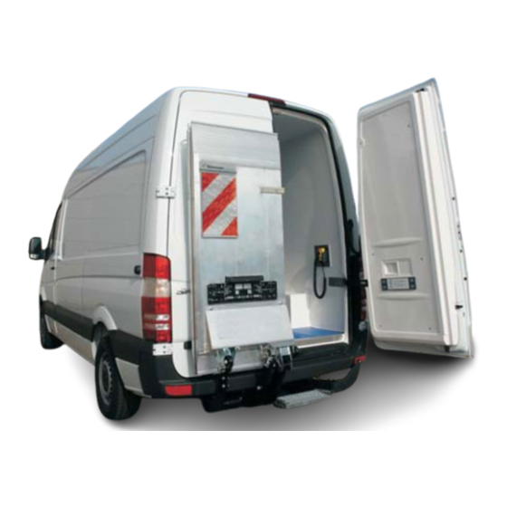
Liftgate for dodge promaster
Hide thumbs
Also See for GPC X1-LDF:
- Installation manual (76 pages) ,
- User manual (50 pages) ,
- Installation manual (75 pages)

Related Manuals for Maxon GPC X1-LDF


Summary of Contents for Maxon GPC X1-LDF
- Page 1 GPC X1-LDF Liftgate Installation Manual for Dodge ProMaster LIFT CORP. 11921 Slauson Avenue Santa Fe Springs, CA 90670-2221 P 800.227.4116 / 562.464.0099 Date 03.2024 F 888.771.7713 Art. No. 20 913 325...
- Page 2 Contact information MAXON LIFT CORP. Corporate Office 11921 Slauson Avenue Santa Fe Springs, CA 90670-2221 P 800.227.4116 / 562.464.0099 F 888.771.7713 Customer Service / Parts USA/Canada Mexico P 800.227.4116 F 888.771.7713 P 01.664.231.6039...
-
Page 3: Table Of Contents
Contents Contact information ....................II Contents ........................III Safety ........................1 1.1 Intended use ....................1 1.2 Requirements for personnel ................1 1.3 Requirements for installation and commissioning .......... 2 1.4 Fundamental hazards ..................2 1.5 Emergency procedure ..................2 1.6 Presentation of warning notices .............. - Page 4 4.2.3 Fastener 20 908 311................24 4.3 Securing the lifting gear to the vehicle ............25 4.4 Securing the frame assembly ............... 26 4.5 Connecting the cables to the lifting gear ............27 4.5.1 Installing and connecting the service switch ........27 4.5.2 Installing and connecting the control panel ........
- Page 5 7.1 Hydraulic oil recommendations ..............61 7.2 Painting the lifting gear ................. 61 7.3 Rating plate ....................61 Useful information ....................62 8.1 About the service switch ................62 8.2 Electrical circuit diagram................63 8.3 Hydraulic circuit diagram ................64 8.4 Torque table ....................
-
Page 6: Safety
Safety 1.1 Intended use This liftgate was specially developed for cargo vans. It may be used only on the vehicles for which it was designed. To determine whether the liftgate may be installed on a specific vehicle, please contact ▪ the manufacturer or customer service. -
Page 7: Requirements For Installation And Commissioning
1.3 Requirements for installation and commissioning ▪ Follow the vehicle manufacturer’s current installation guidelines for the relevant vehicle. Pay particular attention to safety instructions and warnings. ▪ Changes to the liftgate’s axle assemblies and to the necessary installation adapters are prohibited. -
Page 8: Presentation Of Warning Notices
1.6 Presentation of warning notices The following types of notices are used in this manual to identify hazards and complications: WARNING ▪ Failure to heed this notice can result in death or serious injury. CAUTION ▪ Failure to heed this notice can result in minor or moderate injury. -
Page 9: Introduction
Introduction 2.1 Scope of delivery IMPORTANT: All illustrations of the lifting gear are shown without factory-installed cables and hydraulic hoses. 2.1.1 Lifting frame and adapters Figure 1 2.1.2 Platform Figure 2 2.1.3 Bridge Plates Article No.: 20 910 374 Figure 3... -
Page 10: Accessories Kit
2.1.4 Accessories kit Figure 4 Figure 5... - Page 11 Parts list – accessories kit Item Part No. Description Standard Qty. 80 000 046 Hexagon nut DIN 934 - M5 - A2 20 908 251 Hexagon flange bolt DIN 6921 - M10x15 - 10.9 - ZN 20 907 616 Ground roller 20 907 615 Bushing d20/16x32...
-
Page 12: Installation Adapter Kit For Dodge Promaster Only
2.1.5 Installation adapter kit for Dodge ProMaster only Figure 6... -
Page 13: Damage During Transport
Parts list Item Part No. Description Standard Qty. 20 908 309 Left mounting bracket For Dodge ProMaster 20 908 310 Right mounting bracket For Dodge ProMaster 20 908 193 Hexagon head screw DIN 931 - M10x110 - 8.8 - FZB Cylinder head screw DIN 912 - M10x90 - 8.8 - ZN - 20 909 327... -
Page 14: Preparing For Installation
Preparing for installation 3.1 Requirements for installation ▪ The vehicle exhaust must not be located at the rear of the vehicle. ▪ Line the vehicle floor with wood panels. For other types of flooring, verify whether installation is possible. ▪ The rear doors must open to a minimum angle of 180°. ▪... -
Page 15: Remove Spare Tire
3.3.1 Remove spare tire ➢ If the vehicle has a spare tire between the rear axle and the rear bumper, remove the tire (see Fig. 7). Figure 7 3.3.2 Move exhaust pipe ➢ If the exhaust pipe is at the rear, move it to the side. -
Page 16: Deactivate Parking Sensors
3.3.5 Deactivate parking sensors ➢ For vehicles with rear parking sensors, the sensors will no longer function correctly once the platform is installed, because the lifting gear interferes with the sensors (see Fig. 10). Figure 10 3.3.6 Remove trailer hitch or step Fig. -
Page 17: Pre-Installing The Installation Adapters
3.5 Pre-installing the installation adapters Required material for Dodge ProMaster Item Part No. Description Standard Qty. 20 908 309 Left mounting bracket For Dodge ProMaster 20 908 310 Right mounting bracket For Dodge ProMaster 20 908 193 Hexagon head screw DIN 931 - M10x110 - 8.8 - FZB Cylinder head screw DIN 912 - M10x90 - 8.8 - ZN -... - Page 18 Figure 12...
-
Page 19: Installing The Cables/Preparation
3.6 Installing the cables/preparation IMPORTANT: Excess cable must not be wound up in a coil but must be placed in slings (Fig. 13). Figure 13 3.6.1 Cable to the platform Route the control unit cable for platform connection (white plastic cover) to the swing-arm assembly in centre of the vehicle (Fig.14). -
Page 20: Routing The Cables To The Front Of The Vehicle
3.6.3 Routing the cables to the front of the vehicle For more information, look online at http://www.taillift.org/en/electrical-vehicle-interface IMPORTANT: Follow the vehicle manufacturer’s installation guidelines. NOTICE ▪ When installing cables, make sure they are safe from chafing. ▪ Do not install cables near heat-dissipating components. Install power cable ➢... - Page 21 Cable for cabin switch unit ➢ Route the cabin switch cable from the accessories kit (Item No. 11) to the driver’s cabin (see Fig. 18). ➢ Connect the cabin switch cable to the 7-pin connector (DIN 72585) from the control unit. click Figure 18 Legend...
-
Page 22: Control Panel Cable On The Control Unit
3.6.4 Control panel cable on the control unit ➢ Route the control unit cable for control panel connection to the right as viewed in the forward direction of travel (see Fig. 19). Figure 19 3.6.5 Handheld control cable on the Control Unit ➢... - Page 23 ➢ The control unit is delivered with the wires already connected. Thus, to route the cable, disconnect the wires on the Control Unit (in the Power pack) as seen in Fig. Figure 21 ➢ Route the cable 20 911 494 from the cargo area, to outside of the vehicle, to the Control Unit (in the power pack).
-
Page 24: Mounting The Bracket For The 3-/2-Button Handheld Control (Optional)
3.6.6 Mounting the bracket for the 3-/2-button Handheld control (optional) ➢ Mount the bracket (1) for the Handheld control (2) on the vehicle wall (3) using, for example, 2 screws or adhesive (see Fig. 23). Figure 23 Legend Item 1 Bracket for Handheld control Item 2 Handheld control... -
Page 25: Aligning The Lifting Gear
3.7 Aligning the lifting gear ➢ Align the lifting gear under the vehicle on a mounting tool or pallet. ➢ Line up the installation adapters on the lifting gear with the manufacturer’s holes in the vehicle chassis (see Fig. 24). Figure 24 3.8 Mounting holes on the vehicle IMPORTANT:... -
Page 26: Installation
Installation 4.1 Positioning the lifting gear ➢ Place the prepared lifting gear (on a pallet) under the vehicle using a suitable means of transport, e.g. pallet truck, forklift, etc. 4.2 Tightening the lifting gear fittings until hand-tight WARNING Installation at crushing and shearing points Fingers are at risk of being crushed or sheared when the lifting gear is installed on the vehicle. - Page 27 Figure 26 Excerpt from parts list: Installation adapter kit Item Part No. Description Standard Qty. DIN 960 - M14x1,5x60 - 10.9 - 20 902 548 Hexagon head screw DIN 961 - M14x1,5x40 - 10.9 - 20 901 691 Hexagon head screw 20 908 098 Holder X1 600E...
-
Page 28: Holder 20 908 098
4.2.2 Holder 20 908 098 Install the holder 20 908 098 in the vehicle by rotating it 90° from the position shown in Fig. 26, then turning it in its correct position for it to hold. See Fig. 27 for reference. Insert in frame Rotate 90°... -
Page 29: Fastener 20 908 311
4.2.3 Fastener 20 908 311 For additional support, connect the fastener to the liftgate and to the frame of the vehicle - see Fig. 30. The fastener is provided without the bottom hole as per Fig. 29, so that it can be drilled accordingly to fit the vehicle frame. Figure 30 Connect to frame with existing hole... -
Page 30: Securing The Lifting Gear To The Vehicle
4.3 Securing the lifting gear to the vehicle ➢ Secure the completely premounted lifting gear (with adapters) to the vehicle and tighten to a torque of 180 Nm for both front and back connections (refer to torque table on page 65 and Fig. 32). 180Nm on both sides of the liftgate Figure 32... -
Page 31: Securing The Frame Assembly
4.4 Securing the frame assembly ➢ Secure the installation adapters to the lifting gear and tighten to the specified torque of 46 Nm (refer to torque table on page 65 and Fig. 33). The layout of the axles is symmetric, so please follow the same process on the other side as well. 46 Nm 46 Nm Figure 33... -
Page 32: Connecting The Cables To The Lifting Gear
4.5 Connecting the cables to the lifting gear 4.5.1 Installing and connecting the service switch ➢ Disconnect the service switch box from the cable by loosening the screw terminals in the housing (see Fig. 34). Legend Terminal 30 Black cable Terminal Y1 Blue cable Terminal KM... -
Page 33: Installing And Connecting The Control Panel
4.5.2 Installing and connecting the control panel WARNING Penetration of water Over the long term, the improper installation of cables can result in water penetrating the control panel and causing it to malfunction. Risk of serious injury in subsequent operation. ▪... - Page 34 X = distance from border of vehicle 400mm ± 100mm ” ± 3 ”) Figure 36 ➢ Disassemble the control panel SUPERSEAL connector and, if appropriate, the control unit SUPERSEAL connector so that the control panel cable can be routed to the control unit cable via openings.
- Page 35 ➢ Using the release tool, release the safety guard from the socket housing and pin housing (see Fig. 39 and Fig. 40). Figure 39 Figure 40 For the socket housing, Fig. 2 Fig. 3 release the latches on the contact pins and pull the wires out of the back of the housing (see Fig.
-
Page 36: Connecting The Cables (Front Of Vehicle)
Legend Item 1 Connector from control panel for connection to control unit Item 2 Connector from control unit for connection to control panel click! Figure 46 4.5.3 Connecting the cables (front of vehicle) WARNING Vehicle battery short-circuit Improper connection of the device to the vehicle battery can cause a short-circuit and explosion of the battery. -
Page 37: Unpacking The Platform
Figure 48 Item No. Part No. Description Qty. 20 906 975 Cabin switch unit cable 12 m with VEHH connector 20 906 974 Cabin switch 4.6 Unpacking the platform ➢ Check the scope of delivery for completeness (see pages 4–8). IMPORTANT: Dispose of all packing materials in accordance with environmental regulations. -
Page 38: Raising The Platform
4.7 Raising the platform ➢ Lift the platform using suitable means, e.g. crane, assembly table, or pallet truck and pallet (see Fig. 49). Figure 49... -
Page 39: Installing The Platform
4.8 Installing the platform WARNING Installation at crushing and shearing points Fingers are at risk of being crushed or sheared when the platform is installed on the lifting gear. ▪ Be careful at the connecting points between the platform and lifting gear. ➢... - Page 40 Excerpt from parts list: accessories kit Item No. Part No. Description Standard Qty. 20 840 117 O-ring 40.65 x 5.33 ➢ Loosen the platform stop (1) and push it toward the vehicle (see Fig. 52). Figure 52 Legend Item 1 Platform stop ➢...
- Page 41 ➢ Align the top bearing points of the platform (platform attachment points) with the swing- arm bearing points (top attachment points of the lifting gear) (see Fig. 54). Figure 54 ➢ Insert the two pins (a, b) through the top attachment points of the platform and the attachment points of the swing-arm assembly.
- Page 42 ➢ Lift the tip of the platform until the closing-rod bearing point (attachment point for the closing rod) is aligned with the swing-arm bearing point (bottom attachment point on the platform) (see Fig. 56). IMPORTANT: If necessary, slightly retract or extend the closing rod. Figure 56 ➢...
-
Page 43: Mounting The Platform Lock On The Closing Arm
➢ Move the 6 pre-fitted O-rings (accessories kit parts list – Item No. 10) into their correct positions (see Fig. 58). IMPORTANT: All bearing points are sealed with O-rings. Figure 58 Fig. 9 Excerpt from parts list: accessories kit Item No. Part No. Description Standard Qty. -
Page 44: Mounting The Ground Rollers
➢ Mount the screw (1) for the platform lock, including the spring washer (2), washers (3), and sleeve (4), on the platform bearing (see Fig. 60). Legend Item 1 Hexagon head screw Item 2 Spring washer Item 3 Washer Item 4 Sleeve Figure 60 Fig. -
Page 45: Connecting The Platform To The Electrical System
4.11 Connecting the platform to the electrical system 4.11.1 Connecting the platform cable to the electrical system ➢ Connect the platform cable connector (1) to the control unit connector (2) (see Fig. 62). IMPORTANT: The control unit connector is identified by the white plastic cover on the cable. -
Page 46: Connecting The License Plate Light
4.11.2 Connecting the license plate light ➢ Find the cable connection point for the license plate light in the column (a) on the ProMaster (see Fig. 63). Figure 63 Fig. 13 ➢ Route the license plate light cable (2) (cable outlet from platform’s aluminum torsion box) along the closing arm (see Fig. -
Page 47: Mounting The License Plate Holder
4.12 Mounting the license plate holder ➢ Mount the license plate holder below the license plate light. IMPORTANT: When positioning the holder, make sure the license plate is sufficiently illuminated. 4.13 Mounting the bridge plates (20 910 374) ➢ Fasten the bridge plate with the non-skid coating (2) on the right side. The non-skid coating must face upward when the bridge plate is folded shut (see Fig. - Page 48 ➢ Close the liftgate (place in driving position). ➢ Align the warning flag holder (14c). IMPORTANT: Comply with the mounting specifications. ➢ Transfer the existing holes in the warning flag holder to the platform and pre-drill holes for the 2 blind rivets. ➢...
- Page 49 ➢ Move the liftgate to the horizontal position. ➢ Fold out (open) the liftgate. ➢ Bring the open liftgate as far as necessary into the vertical position to comfortably mount the right warning flag. CAUTION Not a normal operating position Risk of injuring yourself or damaging the vehicle or liftgate.
-
Page 50: Affixing The Danger Notice Sticker
4.15 Affixing the danger notice sticker ➢ Affix the danger notice sticker “Safe handling of the liftgate.” IMPORTANT: This sticker is supplied with all new liftgates. The installing company must place it in an easily visible location on the inside of the vehicle cargo area. The danger notice sticker uses pictograms to indicate potential incorrect and correct use of the liftgate. -
Page 51: Adjusting The Liftgate
Adjusting the liftgate 5.1 Adjusting the lift height to vehicle floor with lifting cylinder Adjust the platform to the desired position in relation to the vehicle floor by turning the lifting cylinder piston head (pos. 1) to the left (platform rises), or to the right (platform lowers). See Fig. - Page 52 ➢ If the tilting cylinder head (pos. 1) is turned to the left, the platform tip moves towards the vehicle’s body. ➢ If the tilting cylinder head (pos. 1) is turned to the right, the platform tip moves away from the vehicle’s body. Figure 71 Legend Pos.
-
Page 53: Aligning The Platform Parallel To The Vehicle Floor (Non-Foldable Section)
5.3 Aligning the platform parallel to the vehicle floor (non-foldable section) NOTICE ▪ If no readjustment is necessary, make sure that the screws (1 and 3) are securely tightened. ➢ To align the platform parallel to the vehicle floor, adjust the lifting gear using the left- hand adjustment fork (adjustment screw accessible from above) (see Fig. - Page 54 Figure 73 ▪ When finished adjusting, tighten the bolt (3) for securing the torsion bar to 115 Nm (refer to torque table on page 65 and see Fig. 74). Figure 74...
-
Page 55: Aligning The Platform (Fold-Over Section) Parallel To The Vehicle Floor
5.4 Aligning the platform (fold-over section) parallel to the vehicle floor ➢ If necessary, adjust the height of the fold-over section on the right side of the platform using the right-hand adjustment fork (2) (adjustment screw accessible from below) (see Fig. 75). ➢... -
Page 56: Checking The Stop On The Fold-Over Section Of The Platform
5.5 Checking the stop on the fold-over section of the platform ➢ Check the stop on the fold-over section of the platform. IMPORTANT: The roller (1) on the support arm (2) must remain against the stop (3) throughout the entire lifting process. If necessary, loosen the stop (3) and shift it slightly by loosening 2 cheese-head screws (4). -
Page 57: Setting The End Stop For The Closed Platform
5.6 Setting the end stop for the closed platform The end stop for the platform in the closed position is mounted on the closing arm. The platform requires no additional stops on the vehicle. IMPORTANT: Adjust the platform so that it stands vertically behind the vehicle when closed and in the driving position. - Page 58 ➢ Retighten the 2 screws (1) on the clamping plate (2) on the platform stop to a torque of 195 Nm (see Fig. 80). Figure 80 Fig. 20 ➢ When you reclose the platform, it will stand vertically behind the vehicle (see Fig. 81).
-
Page 59: Adjusting The Stopper For Fastening The Platform
5.7 Adjusting the stopper for fastening the platform The stopper fastens the right-hand fold-over section of the closed platform and keeps the platform from hitting the vehicle while driving. IMPORTANT: Make the adjustment with the platform folded and closed (driving position). ➢... -
Page 60: Adjusting The Support Arm For The Driving Position Using The Bowden Cable
5.8 Adjusting the support arm for the driving position using the Bowden cable Adjust the support arm (1) so that it can be pulled as close to the vehicle as desired when the platform is closed. The adjustment is made outside at the Bowden cable (2) and, if applicable, also at the screw on the lever (3). -
Page 61: Programming The Tilt Sensor
5.9 Programming the tilt sensor Before the first operation of the platform, it is necessary to program the tilt sensor to ensure that the tilting functions are working properly. This is done by pressing a combination of buttons on the control panel (a) (see Fig. 85). ➢... -
Page 62: Testing The Liftgate
Testing the liftgate 6.1 Function test ➢ Test: opening, lifting, lowering, tilting down, tilting up, closing CAUTION Platform at ground level In the fully lowered position, the platform is easily overlooked and may cause people to trip, resulting in injury. ▪... -
Page 63: Load Tests
6.3 Load tests WARNING High loading of components Incorrect installation or defective components may cause components to fail and break. Risk of injury when operating the liftgate. ▪ Perform all the load tests specified here. 6.3.1 Static test ➢ Operate the horizontal platform to the height of the vehicle floor. ➢... -
Page 64: Explanation Of Diagnostic Led On The Control Unit
6.4 Explanation of diagnostic LED on the control unit Cabin switch in LED monitoring function driver’s cabin or fast flashing key switch flashing Platform closed (90°) Platform closed Platform open (90° to 60°) Platform open (60° to 0°) Platform tilted down (0° to -10°) Switch being actuated * Sensor disconnected Data-wire disconnected... -
Page 65: Checking Tilt Sensors S1 And S2 In The Platform
6.4.1 Checking tilt sensors S1 and S2 in the platform Platform closed and liftgate switched on → LED on ▪ -Power supply is functioning correctly. Platform position → 0° to approx. 60°: ▪ -LED off -Tilt sensor S1 in switching position is functioning correctly. -Corner lights are activated. -
Page 66: Recommendations And Instructions Regarding The Liftgate
Recommendations and instructions regarding the liftgate IMPORTANT: To ensure safe operation of the liftgate read the safety instructions and warnings in the accompanying user manual. 7.1 Hydraulic oil recommendations HLPD 22 (ISO-VG 22) “detergent” so that free water remains emulsified (e.g. to prevent ice formation in winter) and to improve oil film adhesion. -
Page 67: Useful Information
Useful information 8.1 About the service switch Service switch extern box The service switch is part of the control unit – mounted in a housing (box) – and enables trained service personnel to control and test the functioning of the liftgate directly (see Fig. -
Page 68: Electrical Circuit Diagram
8.2 Electrical circuit diagram Figure 90... -
Page 69: Hydraulic Circuit Diagram
8.3 Hydraulic circuit diagram Figure 91... -
Page 70: Torque Table
8.4 Torque table Valid torque table for all the bolts and screws supplied and installed on our liftgates Screw size Tightening torque Thread sizes Tightening torque in Nm DIN 3852 in Nm ± 10% ± 10% G1/4“ G3/8“ G1/2“ Union nuts M16 x 1.5 M18 x 1.5 Plugs... -
Page 71: Operation Using The Control Panel
8.6 Operation using the control panel From the control panel, all functions are initiated by pressing two different pushbuttons simultaneously. The diagram shows which buttons are responsible for each individual function: Figure 93 8.7 Operation using the optional handheld control The 3-button handheld control can be used to operate the lifting and lowering functions as well as the tilting up and down functions when the platform is open.
Need help?
Do you have a question about the GPC X1-LDF and is the answer not in the manual?
Questions and answers