Sign In
Upload
Manuals
Brands
Maxon Manuals
Automobile Accessories
GPC X1-LDF
Maxon GPC X1-LDF Manuals
Manuals and User Guides for Maxon GPC X1-LDF. We have
4
Maxon GPC X1-LDF manuals available for free PDF download: Installation Manual, User Manual
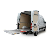
Maxon GPC X1-LDF Installation Manual (76 pages)
Liftgate, Mercedes Benz Sprinter
Brand:
Maxon
| Category:
Automobile Accessories
| Size: 9 MB
Table of Contents
Santa Fe Springs, CA
3
Table of Contents
4
1 Safety
7
Intended Use
7
Requirements for Personnel
7
Requirements for Installation and Commissioning
8
Fundamental Hazards
8
Emergency Procedure
8
Presentation of Warning Notices
9
2 Introduction
10
Scope of Delivery
10
Lifting Gear
10
Platform
10
Bridge Plates (20 909 431)
10
Accessories Kit
11
Installation Adapter Kit (22 911 216)
13
Damage During Transport
14
3 Preparing for Installation
15
Requirements for Installation
15
Lifting the Vehicle
15
Preparing the Vehicle
15
Remove Spare Tire
16
Move Exhaust Pipe
16
Mount Supplementary Battery
16
Install Standard Bumper on Mercedes Sprinter
16
Deactivate Parking Sensors
16
Remove Trailer Hitch or Step
17
Unpacking the Lifting Gear, Installation Adapters, and Accessories Kit
17
Pre-Installing the Installation Adapters
17
Installing the Cables/Preparation
21
Cable to the Platform
21
Cable for the Service Switch
21
Routing the Cables to the Front of the Vehicle
22
Control Panel Cable on the Control Unit
24
Handheld Control (Optional)
24
Aligning the Lifting Gear
26
Mounting Holes on the Vehicle
27
4 Installation
28
Positioning the Lifting Gear
28
Tightening the Lifting Gear Fittings until Hand-Tight
29
Securing the Lifting Gear to the Vehicle
32
Laterally Aligning the Lifting Gear
33
Securing the Axle Assemblies
33
Securing the Installation Adapters
33
Connecting the Cables to the Lifting Gear
34
Installing and Connecting the Service Switch
34
Installing and Connecting the Control Panel
35
Connecting the Handheld Control (Optional)
39
Mounting the Bracket for the Handheld Control (Optional)
39
Connecting the Cables (Front of Vehicle)
39
Unpacking the Platform
42
Raising the Platform
42
Installing the Platform
43
Mounting the Platform Lock on the Closing Arm
47
Mounting the Ground Rollers
48
Installing Supports (Vehicle-Dependent)
49
Connecting the Platform to the Electrical System
49
Connecting the Platform Cable to the Electrical System
49
Connecting the License Plate Light
50
Mounting the License Plate Holder
51
Mounting the Bridge Plates (20 909 431)
51
Mounting the Warning Flags
51
Affixing the Danger Notice Sticker
54
5 Adjusting the Liftgate
55
Setting the Lift Height to the Vehicle Floor Level Using the Adjustable Stop on the Axle Assembly
55
Aligning the Platform Parallel to the Vehicle Floor
55
Aligning the Platform (Foldover Section) Parallel to the Vehicle Floor
56
Checking the Stop on the Foldover Section of the Platform
58
Setting the End Stop for the Closed Platform
59
Adjusting the Stopper for Fastening the Platform
61
Adjusting the Support Arm for the Driving Position Using the Bowden Cable
61
Programming the Tilt Sensor
62
6 Testing the Liftgate
64
Function Test
64
Testing the Operating Speed
64
Vertical Speed
64
Closing and Opening Speed (90° to 10°)
64
Tilting Speed (10° to -10°)
64
Load Tests
65
Static Test
65
Dynamic Test
65
Testing against Lifting an Overload
65
Testing the Safety Devices
65
Explanation of Diagnostic LED on the Control Unit
66
Checking Tilt Sensors S1 and S2 in the Platform
67
Checking Pressure Switch S4
67
Entry in Inspection Record Book
67
7 Recommendations and Instructions Regarding the Liftgate
68
Hydraulic Oil Recommendations
68
Painting the Lifting Gear
68
Rating Plate
68
8 Useful Information
69
About the Service Switch
69
Assembly Drawings of Installation Adapters
71
Electrical Circuit Diagram
72
Hydraulic Circuit Diagram
73
Torque Table
74
Activating the Liftgate
75
Operation Using the Control Panel
75
Operation Using the Optional Handheld Control
76
Advertisement
Maxon GPC X1-LDF Installation Manual (75 pages)
Brand:
Maxon
| Category:
Automobile Accessories
| Size: 4 MB
Table of Contents
Table of Contents
3
Contents
4
Safety
6
Intended Use
6
Requirements for Personnel
6
Requirements for Installation and Commissioning
7
Fundamental Hazards
7
Emergency Procedure
7
Presentation of Warning Notices
8
Introduction
9
Scope of Delivery
9
Lifting Gear
9
Platform
9
Accessories Kit
10
Installation Adapter Kit 22 911 235 for Ford Transit with Front-Wheel Drive
12
Installation Adapter Kit 22 911 217 for Ford Transit with Rear-Wheel Drive
14
Damage During Transport
15
Preparing for Installation
16
Requirements for Installation
16
Lifting the Vehicle
16
Preparing the Vehicle
16
Remove Spare Tire
17
Move Exhaust Pipe
17
Mount Supplementary Battery
17
Install Bumper Without Step
17
Deactivate Parking Sensors
18
Remove Trailer Hitch or Step
18
Unpacking the Lifting Gear, Installation Adapters, and Accessories Kit
18
Pre-Installing the Installation Adapters
19
Securing Angle Brackets to the Front Installation Adapters
22
Installing the Cables/Preparation
23
Cable to the Platform
23
Cable for the Service Switch
23
Routing the Cables to the Front of the Vehicle
24
Control Panel Cable on the Control Unit
26
Handheld Control Cable on the Control Unit
26
Aligning the Lifting Gear
29
Mounting Holes on the Vehicle
30
Installation
31
Positioning the Lifting Gear
31
Tightening the Lifting Gear Fittings until Hand-Tight
32
Securing the Lifting Gear to the Vehicle
34
Securing the Axle Assemblies
35
Connecting the Cables to the Lifting Gear
36
Installing and Connecting Theservice Switch Extern Box
36
Installing and Connecting the Control Panel
37
Connecting the Cables (Front of Vehicle)
41
Unpacking the Platform
42
Raising the Platform
42
Installing the Platform
43
Mounting the Platform Lock on the Closing Arm
47
Mounting the Ground Rollers
48
Installing Supports (Vehicle-Dependent)
49
Connecting the Platform to the Electrical System
49
Connecting the Platform Cable to the Electrical System
49
Connecting the License Plate Light
50
Mounting the License Plate Holder
51
Mounting the Bridge Plates Set 20 910 374
51
Mounting the Warning Flags
51
Affixing the Danger Notice Sticker
54
Adjusting the Liftgate
55
Hubhöhe zum Fahrzeugboden Einstellen am Hubzylinder
55
Plattform in Fahrstellung Vertikal zum Fahrzeugaufbau Einstellen am Schließzylinderkopf
56
Aligning the Platform Parallel to the Vehicle Floor
57
Aligning the Platform (Foldover Section) Parallel to the Vehicle Floor
59
Checking the Stop on the Foldover Section of the Platform
60
Setting the End Stop for the Closed Platform
61
Adjusting the Stopper for Fastening the Platform
63
Adjusting the Support Arm for the Driving Position Using the Bowden Cable
64
Programming the Tilt Sensor
65
Testing the Liftgate
66
Function Test
66
Testing the Operating Speed
66
Vertical Speed
66
Closing and Opening Speed (90° to 10°)
66
Tilting Speed (10° to -10°)
66
Load Tests
67
Static Test
67
Dynamic Test
67
Testing against Lifting an Overload
67
Testing the Safety Devices
67
Explanation of Diagnostic LED on the Control Unit
68
Checking Tilt Sensors S1 and S2 in the Platform
69
Checking Pressure Switch S4
69
Entry in Inspection Record Book
69
Recommendations and Instructions Regarding the Liftgate
70
Hydraulic Oil Recommendations
70
Painting the Lifting Gear
70
Rating Plate
70
Useful Information
71
About the Service Switches
71
Electrical Circuit Diagram Series 11
72
Hydraulic Circuit Diagram
73
Torque Table
74
Activating the Liftgate
75
Operation Using the Control Panel
75
Operation Using the Optional Handheld Control
75
Maxon GPC X1-LDF Installation Manual (71 pages)
Liftgate for Dodge ProMaster
Brand:
Maxon
| Category:
Lifting Systems
| Size: 3 MB
Table of Contents
Table of Contents
3
Safety
6
Intended Use
6
Requirements for Personnel
6
Requirements for Installation and Commissioning
7
Fundamental Hazards
7
Emergency Procedure
7
Presentation of Warning Notices
8
Introduction
9
Scope of Delivery
9
Lifting Frame and Adapters
9
Platform
9
Bridge Plates
9
Accessories Kit
10
Installation Adapter Kit for Dodge Promaster Only
12
Damage During Transport
13
Preparing for Installation
14
Requirements for Installation
14
Lifting the Vehicle
14
Preparing the Vehicle
14
Remove Spare Tire
15
Move Exhaust Pipe
15
Mount Supplementary Battery
15
Install Bumper Without Step
15
Deactivate Parking Sensors
16
Remove Trailer Hitch or Step
16
Unpacking the Lifting Gear, Installation Adapters, and Accessories Kit
16
Pre-Installing the Installation Adapters
17
Installing the Cables/Preparation
19
Cable to the Platform
19
Cable for the Service Switch
19
Routing the Cables to the Front of the Vehicle
20
Control Panel Cable on the Control Unit
22
Handheld Control Cable on the Control Unit
22
Mounting the Bracket for the 3-/2-Button Handheld Control (Optional)
24
Aligning the Lifting Gear
25
Mounting Holes on the Vehicle
25
Installation
26
Positioning the Lifting Gear
26
Tightening the Lifting Gear Fittings until Hand-Tight
26
Installation Adapters
26
Holder 20 908 098
28
Fastener 20 908 311
29
Securing the Lifting Gear to the Vehicle
30
Securing the Frame Assembly
31
Connecting the Cables to the Lifting Gear
32
Installing and Connecting the Service Switch
32
Installing and Connecting the Control Panel
33
Connecting the Cables (Front of Vehicle)
36
Unpacking the Platform
37
Raising the Platform
38
Installing the Platform
39
Mounting the Platform Lock on the Closing Arm
43
Mounting the Ground Rollers
44
Connecting the Platform to the Electrical System
45
Connecting the Platform Cable to the Electrical System
45
Connecting the License Plate Light
46
Mounting the License Plate Holder
47
Mounting the Bridge Plates (20 910 374)
47
Mounting the Warning Flags
47
Affixing the Danger Notice Sticker
50
Adjusting the Liftgate
51
Adjusting the Lift Height to Vehicle Floor with Lifting Cylinder
51
Adjusting the Platform Vertically to the Vehicle Body with the Tilting Cylinder Head (Driving Position)
51
Aligning the Platform Parallel to the Vehicle Floor (Non-Foldable Section)
53
Aligning the Platform (Fold-Over Section) Parallel to the Vehicle Floor
55
Checking the Stop on the Fold-Over Section of the Platform
56
Setting the End Stop for the Closed Platform
57
Adjusting the Stopper for Fastening the Platform
59
Adjusting the Support Arm for the Driving Position Using the Bowden Cable
60
Programming the Tilt Sensor
61
Testing the Liftgate
62
Function Test
62
Testing the Operating Speed
62
Vertical Speed
62
Closing and Opening Speed (90° to 10°)
62
Tilting Speed (10° to -10°)
62
Load Tests
63
Static Test
63
Dynamic Test
63
Testing against Lifting an Overload
63
Testing the Safety Devices
63
Explanation of Diagnostic LED on the Control Unit
64
Checking Tilt Sensors S1 and S2 in the Platform
65
Checking Pressure Switch S4
65
Entry in Inspection Record Book
65
Recommendations and Instructions Regarding the Liftgate
66
Hydraulic Oil Recommendations
66
Painting the Lifting Gear
66
Rating Plate
66
Useful Information
67
About the Service Switch
67
Electrical Circuit Diagram
68
Hydraulic Circuit Diagram
69
Torque Table
70
Activating the Liftgate
70
Operation Using the Control Panel
71
Operation Using the Optional Handheld Control
71
Advertisement
Maxon GPC X1-LDF User Manual (50 pages)
liftgate
Brand:
Maxon
| Category:
Automatic Barriers
| Size: 4 MB
Table of Contents
Table of Contents
3
General
5
Purpose of the User Manual
5
Accompanying Documents
5
Description of the MAXON Liftgate
5
Overview of the MAXON GPC X1-LDF Liftgate
6
Overview of the MAXON GPC X1-LD Liftgate
7
Description of the MAXON Liftgate Components
8
Information, Spare Parts Ordering, and Warranty Services Using the Liftgate Serial Number and Rating Plate
9
The Liftgate Serial Number and the Rating Plate
9
Safety
10
Presentation of Warning Notices
10
Fundamental Hazards (Hazards Caused by the Liftgate)
11
Emergency Procedure
12
Safety Devices on the Liftgate
12
Intended Use
12
Responsibilities of Operating Company and Requirements for Operator
13
Commissioning
14
Handling and Behavior During Operation
17
2.10 Danger Notice Sticker "Safe Handling of the Liftgate
20
2.11 Permissible Loads
21
2.12 Load Diagram
22
Operation of the GPC X1-LD and GPC X1-LDF Liftgates
23
Activating the Liftgate
23
Operation Using the Control Panel (Membrane Switch)
23
Operation Using the Optional Foot Controls
24
3.4 Operation Using the Optional Handheld Control with Spiral Cable
25
Operating Positions and Safety Distances When Using the Optional Handheld Control with Spiral Cable
26
Using the Bridge Plates
27
Detailed Operating Sequence for the GPC X1-LDF
28
Maintenance
32
Daily Visual Inspections
32
Annual Inspection
32
Care, Maintenance, Testing, and Repair
32
Fault Diagnosis and Fault Elimination
36
Explanation of Diagnostic LED in the Control Unit
36
Checking the Tilt Sensor in the Platform
36
Checking Pressure Switch S4
36
Support for Fault Diagnostics and Elimination
37
When Electric Motor Is Operated Continuously "Liftgate Cannot be Switched off
39
Emergency! Platform Moved by Mechanical Means
40
Malfunction
40
Decommissioning, Disassembly, and Disposal
41
Electrical Circuit Diagram
44
Hydraulic Circuit Diagram
45
Warranty, Liability Exclusions, Copyright
46
Warranty
46
Purchase Part Warranty
46
Liability Exclusions
47
Copyright
47
Notes
48
Advertisement
Related Products
Maxon GPC X1-LD
Maxon GPT-4
Maxon GPTWR-3
Maxon GPTWR-5
Maxon GPTLR-25
Maxon GPTLR-33
Maxon GPTLR-44
Maxon GPSLR-33
Maxon GPSLR-44
Maxon GPSTLR-33
Maxon Categories
Radio
Lifting Systems
Two-Way Radio
Music Pedal
Automobile Accessories
More Maxon Manuals
Login
Sign In
OR
Sign in with Facebook
Sign in with Google
Upload manual
Upload from disk
Upload from URL