L-Acoustics X8 Rigging Manual
Hide thumbs
Also See for X8:
- Owner's manual (85 pages) ,
- User manual (34 pages) ,
- Rigging manual (55 pages)

Subscribe to Our Youtube Channel
Related Manuals for L-Acoustics X8


Summary of Contents for L-Acoustics X8
- Page 1 rigging manual 1.0 (EN)
- Page 2 Document reference: X8 rigging manual (EN) version 1.0 Distribution date: September 24, 2015 © 2015 L-ACOUSTICS. All rights reserved. No part of this publication may be reproduced or transmitted in any form or by any means without the express written consent of the...
-
Page 3: Table Of Contents
Contents Safety................................5 Instructions..............................5 Symbols..............................5 Welcome................................6 System components.............................7 Mechanical safety...............................8 Rigging system description..........................10 X8................................. 10 Elements for flying and wall-mounting....................... 11 X-US8 and X-UL8.......................... 11 X-UTILT............................14 X-BAR............................14 Elements for pole-mounting........................16 Pole socket........................... 16 EMBi............................17 Subwoofer............................ 17 Rigging procedures............................18... - Page 4 EMBi specifications..........................56...
-
Page 5: Safety
Respect the Working Load Limit (WLL) of third party equipment. L-Acoustics is not responsible for any rigging equipment and accessories provided by third party manufacturers. Verify that the Working Load Limit (WLL) of the suspension points, chain hoists and all additional hardware rigging accessories is respected. -
Page 6: Welcome
Welcome Welcome Thank you for purchasing the L-Acoustics X8. As part of a continuous evolution of techniques and standards, reserves the right to change the specifications of its products and the content of its document without prior notice. Please check on a regular basis to download the latest document and software updates. -
Page 7: System Components
3D acoustical and mechanical modeling software. Other X8 system components All the other components of the system are presented in the X8 user manual, document intended to describe the enclosure configurations and connection schemes. X8 rigging manual (EN) version 1.0... -
Page 8: Mechanical Safety
Mechanical safety Maximum configurations The X8 rigging system complies with 2006/42/EC: Machinery Directive. It has been designed following the guidelines of BGV-CI. 2006/42/EC: Machinery Directive specifies a safety factor of 4:1 against the rupture. The limits specified in the tables below are given with a safety factor of —... - Page 9 Soundvision calculations are based on usual environmental conditions. A higher safety factor is recommended with factors such as extreme high or low temperatures, strong wind, prolonged exposition to salt water, etc. Always consult a rigging specialist to adopt safety practices adapted to such a situation. X8 rigging manual (EN) version 1.0...
-
Page 10: Rigging System Description
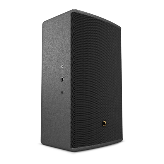
Rigging system description Rigging system description X8 features a M8 DIN580 threaded insert designed to implement a secondary safety. The logo on the enclosure front can be rotated to adapt to every configuration. X8 features an ergonomic handle for easy transportation. -
Page 11: Elements For Flying And Wall-Mounting
Elements for flying and wall-mounting X-US8 and X-UL8 X8 can be fitted with a short U-bracket, X-US8, or a long U-bracket, X-UL8. The brackets are secured in the enclosure inserts with two threaded knobs. A spring-lock safety mechanism secures the knobs in the U-brackets. - Page 12 Rigging system description X-US8 and X-UL8 can be used for wall-mounting, ceiling-mounting or flying X8. With the short U-bracket in horizontal position, the enclosure applies a diagonal force of 179 dekanewtons on the anchoring points. Apply the appropriate safety factor.
- Page 13 X-US8 features an additional hole on the sides to closely fit the enclosure and to optimize visual impact. When using the additional hole, consider the maximum site angle available. Maximum angles (p.34). The knobs shall be stored in the U-brackets. X8 rigging manual (EN) version 1.0...
-
Page 14: X-Utilt
5° steps. The azimuth angle can be adjusted with the U-bracket. X-UTILT shall only be used vertically. X-BAR X-BAR is a rigging bar for flying the X8. The rigging system consists of a threaded axis with a cam lever. X8 rigging manual (EN) version 1.0... - Page 15 Rigging system description X-BAR shall be secured to the inserts on the enclosure, perpendicular to the front. Five angulation holes are available. X8 rigging manual (EN) version 1.0...
-
Page 16: Elements For Pole-Mounting
Rigging system description X-BAR is compatible with a CMU 1 T 12 mm shackle (provided) and with CLAMP250. Elements for pole-mounting Pole socket X8 features a 35 mm pole-socket integrated in the handle. X8 rigging manual (EN) version 1.0... -
Page 17: Embi
Rigging system description EMBi EMBi is a pole-mount adapter for X-US8 (35 mm pole). The site angle can be adjusted with the U-bracket. Subwoofer SB15m features a 35 mm pole socket. X8 rigging manual (EN) version 1.0... -
Page 18: Rigging Procedures
In this case, the rigging procedure will require 2 operators. The procedure is shown with X-UL8 in horizontal position. The same procedure applies for X-UL8 in vertical position or in ceiling-mounting configuration and X-US8 in vertical position or in ceiling-mounting configuration. X8 rigging manual (EN) version 1.0... - Page 19 When securing the U-bracket horizontally, make sure the hooks are oriented upwards. 3. Lift the enclosure by the knobs and place it inside the U-bracket. Adjust the knobs on both sides so that the safety washer is between the hook and the enclosure. X8 rigging manual (EN) version 1.0...
- Page 20 Rigging procedures 4. Push until the knobs are locked inside the spring-lock safety mechanism. SHLAK! 5. Set the site angle. Use the screw as a reference point to read the label. X8 rigging manual (EN) version 1.0...
- Page 21 Rigging procedures 6. Tighten the knobs. Make sure the enclosure is steady. X8 rigging manual (EN) version 1.0...
- Page 22 Do not unscrew the knobs all the way. 2. On both sides, pull on the safety mechanism while lifting the enclosure by the knobs to release it. 3. Remove the U-bracket from the wall. X8 rigging manual (EN) version 1.0...
-
Page 23: Using A U-Bracket With X-Utilt
Additionnal safety for flown arrays When flying an array, use the M8 DIN580 threaded insert to implement a secondary safety. The procedure is shown with X-UL8 The same procedure applies for X-US8. X8 rigging manual (EN) version 1.0... - Page 24 X-UTILT can only be used vertically. 1. Secure X-UTILT to the wall using M10 screws. 2. Secure the U-bracket to X-UTILT. When using X-US8, the bracket must be secured with the label on top. X8 rigging manual (EN) version 1.0...
- Page 25 Always use the central insert. 4. Choose the site angle and secure the rigging arm to X-UTILT. Refer to the angles on the label. 0° -5° -10° -15° -20° -25° 30° -35° -40° -45° X8 rigging manual (EN) version 1.0...
- Page 26 6. Lift the enclosure by the knobs and place it inside the U-bracket. Adjust the knobs on both sides so that the safety washer is between the hook and the enclosure. 7. Push until the knobs are locked inside the spring-lock safety mechanism. SHLAK! X8 rigging manual (EN) version 1.0...
- Page 27 Rigging procedures 8. Set the azimuth angle. Use the screw as a reference point to read the label. 9. Tighten the knobs. Make sure the enclosure is steady. X8 rigging manual (EN) version 1.0...
- Page 28 Do not unscrew the knobs all the way. 2. On both sides, pull on the safety mechanism while sliding the enclosure out of the U-bracket. 3. Remove the U-bracket and X-UTILT from the wall. X8 rigging manual (EN) version 1.0...
-
Page 29: Flying With A U-Bracket
Additionnal safety for flown arrays When flying an array, use the M8 DIN580 threaded insert to implement a secondary safety. The procedure is shown with X-US8. The same procedure applies for X-UL8. X8 rigging manual (EN) version 1.0... - Page 30 1. Drive the knobs in the inserts on the enclosure. Stop when the threading is halfway in. 2. Place the U-bracket around the assembly. Adjust the knobs on both sides so that the safety washer is between the hook and the enclosure. X8 rigging manual (EN) version 1.0...
- Page 31 3. Push down until the knobs are locked inside the spring-lock mechanism. SHLAK! Alternatively, use the additional hole on the U-bracket. The hooks on the bracket must be oriented towards the front of the enclosure. X8 rigging manual (EN) version 1.0...
- Page 32 Rigging procedures Make sure the flat washer goes through the hole on the bracket . 4. Tighten the knobs and fly the enclosure with a clamp. X8 rigging manual (EN) version 1.0...
- Page 33 Rigging procedures 5. Loosen the knobs to set the site angle. Use the screw as a reference point to read the label. 6. Tighten the knobs. Make sure the enclosure is steady. X8 rigging manual (EN) version 1.0...
- Page 34 Rigging procedures Maximum angles When using the additional hole on the U-bracket, consider the maximum negative site angle available. -28° X8 rigging manual (EN) version 1.0...
- Page 35 Rigging procedures Disassembly Procedure 1. Place the enclosure on a flat surface. 2. Loosen the knobs. 3. Pull on the safety mechanism and remove the U-bracket from the enclosure. X8 rigging manual (EN) version 1.0...
-
Page 36: Flying With X-Bar
CMU 1 T 12 mm shackle CLAMP250 (optional) min number of operators Additionnal safety for flown arrays When flying an array, use the M8 DIN580 threaded insert to implement a secondary safety. X8 rigging manual (EN) version 1.0... - Page 37 Rigging procedures Assembly Procedure 1. Lay the enclosure on a flat surface. 2. Drive the X-BAR in the insert. 3. Rotate the X-BAR until perpendicular to the front grill. Use the screws as reference points. X8 rigging manual (EN) version 1.0...
- Page 38 4. Tighten the X-BAR. a) Lift the lever and rotate it counter-clockwise. b) Release the lever and rotate it clockwise. c) Repeat until the X-BAR is tightly secured. d) Finally, store the lever on the right. X8 rigging manual (EN) version 1.0...
- Page 39 +24° — Front extension on horizontal enclosure +14° +1° +27° +37° +47° — Rear extension on vertical enclosure -5° -14° +5° -23° -31° — Front extension on vertical enclosure -6° +3° -15° +13° +22° X8 rigging manual (EN) version 1.0...
- Page 40 Rigging procedures 6. Lift the assembly. X8 rigging manual (EN) version 1.0...
- Page 41 Rigging procedures Disassembly Procedure 1. Take down the assembly. 2. Lift the lever and rotate it clockwise. 3. Release the lever and rotate it counter-clockwise. 4. Repeat until the X-BAR can be removed. X8 rigging manual (EN) version 1.0...
-
Page 42: Pole-Mounting With A U-Bracket
Rigging procedures Pole-mounting with a U-bracket type of deployment pole-mounting rigging accessories X-US8 EMBi additional material 35 mm pole min number of operators X8 rigging manual (EN) version 1.0... - Page 43 1. Secure EMBi to the U-bracket with the provided bolts and nuts. 2. Secure the U-bracket to the enclosure using the additional holes. The hooks on the bracket must be oriented towards the front of the enclosure. X8 rigging manual (EN) version 1.0...
- Page 44 Rigging procedures Make sure the flat washer goes through the hole on the bracket. 3. Tighten the knobs, reverse the assembly and mount it on a pole. 4. Tighten EMBi. X8 rigging manual (EN) version 1.0...
- Page 45 5. Loosen the knobs to set the site angle. Consider the maximum positive site angle available. +28° 6. Tighten the knobs. Make sure the enclosure is steady. The assembly can be mounted on a tripod or on a subwoofer. X8 rigging manual (EN) version 1.0...
- Page 46 About this task Remove the assembly from the pole before disassembling the enclosure and the bracket. Procedure 1. Loosen EMBi to remove the assembly from the pole. 2. Remove the bracket from the enclosure. X8 rigging manual (EN) version 1.0...
-
Page 47: Forbidden Configurations
Forbidden configurations Forbidden configurations Forbidden Authorized X8 rigging manual (EN) version 1.0... -
Page 48: Illustrations
Illustrations Illustrations Loudspeaker enclosures passive 2-way coaxial enclosure SB15m high power compact subwoofer Rigging elements CLAMP250 Clamp certified for 250 kg EMBi Pole mount socket X8 rigging manual (EN) version 1.0... -
Page 49: Software Applications
X-UTILT U-bracket wallmount for X series with tilt adjustment X-BAR Rigging bar for X series X-UL8 Long U-bracket for X8 X-US8 Short U-bracket for X8 Software applications Soundvision 3D acoustical and mechanical modeling software X8 rigging manual (EN) version 1.0... -
Page 50: Specifications
Specifications Specifications X8 specifications Description X8 passive 2-way coaxial enclosure, amplified by LA4X / LA8. Usable bandwidth (-10 dB) 60 Hz - 20 kHz Maximum SPL 127 dB ([X8]) Nominal directivity Vertical: Axisymmetric 100° Monitoring angle 35° Transducers 1 × 8" weather-resistant, bass-reflex laminar vents. - Page 51 16.7 in / 9.8 in / 10.4 in Monitor H/W/D 278 mm / 424 mm / 306 mm 10.9 in / 16.7 in / 12 in 264 mm / 10.4 in 250 mm / 9.8 in 306 mm / 12 in X8 rigging manual (EN) version 1.0...
-
Page 52: X-Ul8 Specifications
High grade steel with anti-corrosion coating X-UL8 dimensions 529 mm / 20.8 in 200 mm / 7.9 in Ø M10 487 mm / 19.2 in 53 mm / 2.1 in 80 mm / 3.1 in X8 rigging manual (EN) version 1.0... -
Page 53: X-Us8 Specifications
High grade steel with anti-corrosion coating X-US8 dimensions 355 mm / 14 in 100 mm / 3.9 in Ø M10 318.2 mm / 12.5 in 53 mm / 2.1 in 80 mm / 3.1 in X8 rigging manual (EN) version 1.0... -
Page 54: X-Bar Specifications
Rigging bar for X series Weight (net) 1.1 kg / 2.4 lb Material High grade steel with anti-corrosion coating X-BAR dimensions 13 mm / 0.5 in 83 mm / 3.3 in 185 mm / 7.3 in X8 rigging manual (EN) version 1.0... -
Page 55: X-Utilt Specifications
1.5 kg / 3.3 lb Material High grade steel with anti-corrosion coating X-UTILT dimensions 200 mm / 7.9 in Ø M10 88 mm / 3.5 in 300 mm / 11.8 in 65 mm / 2.6 in X8 rigging manual (EN) version 1.0... - Page 56 Description Pole-mount socket Weight (net) 0.5 kg / 1.1 lb Material High grade steel with anti-corrosion coating EMBi dimensions 115.5 mm / 4.5 in 46 mm / 1.8 in 35 mm / 1.4 in X8 rigging manual (EN) version 1.0...
Need help?
Do you have a question about the X8 and is the answer not in the manual?
Questions and answers