SOLOPORT SP40/5-1 Assembly Instructions Manual
Solar carport
Hide thumbs
Also See for SP40/5-1:
- Assembly instructions manual (15 pages) ,
- Assembly instructions manual (52 pages) ,
- Assembly instructions manual (20 pages)
Advertisement
Available languages
Available languages
Table of Contents
MONTAGEANLEITUNG
ASSEMBLY INSTRUCTIONS
INSTRUCTIONS DE MONTAGE
Solarcarport
Solar carport
Carport solaire
SP40/5-1 | SP40/5-1A | SP40/5-1W | SP40/5-1AW
SPG5 | SPG5-A | SPG5-W | SPG5-AW
SPG | SPG-A | SPG-W | SPG-AW
Bitte lesen Sie vor der Verwendung des Produktes unbedingt dieses Handbuch und folgen den darin enthaltenen Anweisungen!
Please read this manual before using the product and follow the instructions it contains!
Veuillez lire ce manuel avant d'utiliser le produit et suivre les instructions qu'il contient!
Advertisement
Table of Contents

Related Manuals for SOLOPORT SP40/5-1


Summary of Contents for SOLOPORT SP40/5-1
- Page 1 Solarcarport Solar carport Carport solaire SP40/5-1 | SP40/5-1A | SP40/5-1W | SP40/5-1AW SPG5 | SPG5-A | SPG5-W | SPG5-AW SPG | SPG-A | SPG-W | SPG-AW Bitte lesen Sie vor der Verwendung des Produktes unbedingt dieses Handbuch und folgen den darin enthaltenen Anweisungen! Please read this manual before using the product and follow the instructions it contains! Veuillez lire ce manuel avant d‘utiliser le produit et suivre les instructions qu‘il contient!
- Page 2 STÜCKLISTE A Stützpfosten 1 B Stützpfosten 2 x 1* x 1* C Stützpfosten 3 D Stützpfosten 4 x 1* x 1* E Längsträger F Standfuß x 1* x 2* G M16 x 130 Sechskantschraube H Querträger x 16 x 8* I Querträgerklemme J Kreuzklemme x 32...
- Page 3 K Längsträger mit Regenrinne (kurz / lang) L Verbindung Regenrinne x 3* x 3* M Solarmodul N Äußere Klemme x 12 x 16 x 12* x 8* O Mittlere Klemme P Erdungsklemme x 16 x 24* x 4* Q Regenrinne R Vierkantprofil x 1* x 9*...
- Page 4 U Schaltschrank V LED-Leuchte W Bewegungsmelder X Erdspieß Für die Montageanleitung der Anbaufelder, siehe Seite 10. Für die Montageanleitung und Stückliste der Regenrinne, siehe Seite 13. Vor Aufstellung des Carports muss gewährleistet sein, dass der Standort eine ebene und tragfähige Bodenbeschaffenheit aufweist.
- Page 5 MONTAGE GRUNDFELD A-D 2 x E 2 x F 4 x G 16 x T 4 x Legen Sie die Aluminiumprofile für das Seitengerüst auf den Boden. Befestigen Sie die Standfüße (F) an den freien Enden der Befestigen Sie die Stützpfosten (A, B, C, D) mit dem Längsträger (E). Nutzen Stützpfosten (A, B, C, D).
- Page 6 x = 745 mm 2 1 x H 6 x I 24 x Montieren Sie die restlichen Querträger (H) in gleichmäßigen Abständen von 745 mm (x) zwischen den ersten beiden Querträgern. Gehen Sie hierbei wie in Schritt 2-1 vor. 2-3 1 x L 4 x J 32 x K 4 x...
- Page 7 Die Längsträger mit Regenrinne (K) sollten am tiefen Ende des Carportes Verbinden Sie die Längsträger mit Regenrinne (K) mit dem Verbindungsstück 560 mm überstehen. Richten sie den ersten äußeren Längsträger mit (L). Schieben Sie das kurze und lange Stück des Längsträgers mit Regenrinne (K) am Querträgerende aus und montieren sie die 3 weiteren, Regenrinne (K) auf das Verbindungsstück (L) auf.
- Page 8 Schieben Sie das erste Solarmodul (M) von unten nach oben auf die Längsträger mit Regenrinne (K). Richten Sie den inneren Längsträger entsprechend der Breite des Solarmoduls aus und ziehen Sie die Kreuzklemmen (J) fest an. Befestigen Sie das Solarpaneel mit Hilfe der äußeren Klemmen (N) an den außenliegenden Längsträgern mit Regenrinnen (K). Befestigen Sie das Solarpanel mit den mittleren Klemmen (O), siehe Schritt 4-5.
- Page 9 M 9 x N 12 x O 12 x Q 9 x Richten Sie die oberen Längsträger mit Regenrinne (K) nochmals parallel aus. Legen Sie nach jeder Reihe drei Regenrinnen (Q) quer zu den Längsträgern ein, indem Sie die Solarpaneele vorsichtig anheben und die Regenrinnen (Q) darunter schieben. Ziehen Sie die Klemmen (N+O) fest. R 1-2 x S 4 x Das Vierkantprofil (R) wird für zusätzliche Stabilität mit den Vierkantprofil-...
- Page 10 MONTAGE ANBAUFELD A-D 1 x E 1 x F 2 x G 8 x T 2 x Legen Sie die Aluminiumprofile für das Seitengerüst auf den Boden. Befestigen Sie die Standfüße (F) an den freien Enden der Befestigen Sie die Stützpfosten (A, B, C, D) mit dem Längsträger (E). Stützpfosten (A, B, C, D).
- Page 11 x = 745 mm 8 1 x H 6 x I 24 x Montieren Sie die restlichen Querträger (H) mittig zu den Querträgern des Grundfeldes. Gehen Sie hierbei wie in Schritt 2-3 vor. Alle anderen Schritte können aus den Montageschritten des Grundfelds abgeleitet werden. Siehe Seite 6, ab Schritt 3. R 1 x S 4 x Bei den Wohnmobilcarports wird jeweils am vorderen und hinteren...
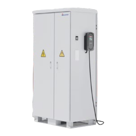
- Page 12 MONTAGE SCHALTSCHRANK, LED-LEUCHTE UND ERDSPIESS V 1 x U 1 x W 1 x X 1 x 10-1 10-2 Positionieren Sie den Schaltschrank (U) an einen der äußeren Stützen Der Schaltschrank (U) sollte so nah wie möglich an dem Standfuß (F) (A oder B).
- Page 13 Benötigtes Werkzeug: STÜCKLISTE - REGENRINNE • Metallbohrer mit 10 mm Aufsatz • Nietenzange oder Zweikomponentenkleber A Halterungen Regenrinne B Regenrinne - unteres Teil C Regenrinne - oberes Teil D Klemme Regenrinne E Seitenteile links / rechts F Wassersammeltopf G Fallrohrbogen 65° H Distanzring I Fallrohr Zwischenstück J Fallrohr...
- Page 14 MONTAGE REGENRINNE A 4 x B 1 x C 1 x D 4 x Führen Sie die vier Klemmen Regenrinne (D) zuerst und dann die Halterungen Ziehen Sie die Innensechskantschraube an, um die Halterung Regenrinne zu Regenrinne (A) in die Längsträger mit Regenrinne ein. befestigen.
-
Page 15: Service & Kontakt
G 2 x H 1 x E 2 x F 1 x J 1 x K 1 x Setzen Sie die Seitenteile als Abschluss links und rechts auf die zusammen- Positionieren sie den Wassersammeltopf (F) so, dass sich der runde Auslass gebaute Regenrinne und verkleben Sie diese mit einen Zeikomponenten- in einer Flucht mit dem Stützpfosten befindet. -
Page 16: Parts List
PARTS LIST A Support post 1 B Support post 2 x 1* x 1* C Support post 3 D Support post 4 x 1* x 1* E Longitudinal beam F Base x 1* x 2* G M16 x 130 hexagon head screw H Cross beam x 16 x 8*... - Page 17 K Longitudinal beam with rain gutter L Rain gutter connection (short / long) x 3* x 3* M Solar module N Outer clamp x 12 x 16 x 12* x 8* O Center clamp P Ground clamp x 16 x 24* x 4* Q Rain gutter R Square profile...
- Page 18 U Electrical cabinet V LED light W Motion detector X Ground spike For the installation instructions for the extensions, see page 10. For the installation instructions and parts list for the rain gutter, see page 13. Before setting up the carport, it must be ensured that the location has a level and stable ground condition. After installation, the carport must be fixed to the ground.
- Page 19 ASSEMBLY BASE FIELD A-D 2 x E 2 x F 4 x G 16 x T 4 x Place the aluminum profiles for the side frame on the ground. Attach the Attach the bases (F) to the free ends of the support posts (A, B, C, D). support posts (A, B, C, D) to the longitudinal beam (E).
- Page 20 x = 745 mm 2 1 x H 6 x I 24 x Install the remaining cross beams (H) at even intervals of 745 mm (x) between the first two cross beams. Proceed as described in step 2-1. 2-3 1 x L 4 x J 32 x K 4 x...
- Page 21 The longitudinal beams with gutter (K) should protrude 560 mm at the deep Connect the longitudinal beam with rain gutter (K) to the connecting piece end of the carport. Align the first outer longitudinal beam with rain gutter (K) (L). Slide the short and long piece of the longitudinal beam with rain gutter with the end of the cross beam and fit the 3 other long longitudinal beams (K) onto the connecting piece (L).
- Page 22 Slide the first solar module (M) from bottom to top onto the longitudinal beams with rain gutter (K). Align the inner longitudinal beam according to the width of the solar module and tighten the cross clamps (J) firmly. Attach the solar panel to the outer longitudinal beams with rain gutters (K) using the outer clamps (N). Fasten the solar panel with the center clamps (O), see step 4-5.
- Page 23 M 9 x N 12 x O 12 x Q 9 x Align the upper longitudinal beams with rain gutter (K) parallel again. After each row, insert three rain gutters (Q) at right angles to the longitudinal beams by carefully lifting the solar panels and sliding the rain gutters (Q) underneath. Tighten the clamps (N+O). R 1-2 x S 4 x The square profile (R) is screwed to the front bases (B) using the brackets...
- Page 24 ASSEMBLY EXTENSION A-D 1 x E 1 x F 2 x G 8 x T 2 x Place the aluminum profiles for the side frame on the ground. Attach the Attach the bases (F) to the free ends of the support posts (A, B, C, D). support posts (A, B, C, D) to the longitudinal beam (E).
- Page 25 x = 745 mm 8 1 x H 6 x I 24 x Fit the remaining cross beams (H) in the center of the cross beams of the base panel. Proceed as described in steps 2-3. All other steps can be derived from the installation steps for the base field. See page 6, from step 3. R 1 x S 4 x A square profile (R) is fitted to the front and rear support posts of the...
- Page 26 ASSEMBLY OF ELECTRIC CABINET, LED LIGHT AND GROUND SPIKE V 1 x U 1 x W 1 x X 1 x 10-1 10-2 Position the electric cabinet (U) on one of the outer posts (A or B). The electric cabinet (U) should be positioned as close as possible to the base (F).
- Page 27 Tools required: PARTS LIST - RAIN GUTTER • Metal drill with 10 mm attachment • Riveting pliers or two-component adhesive A Rain gutter brackets B Rain gutter - lower part C Rain gutter - upper part D Rain gutter clamp E Side panels left / right F Water collection container G Downpipe bend 65°...
- Page 28 RAIN GUTTER ASSEMBLY A 4 x B 1 x C 1 x D 4 x Insert the four rain gutter clamps (D) first and then the rain gutter Tighten the hexagon socket screw to secure the rain gutter bracket. brackets (A) into the longitudinal beams with rain gutter. Hang the two rain gutter parts, lower part (B) and upper part (C) into each Hang the connected gutter sections in the gutter brackets (A).
-
Page 29: Service & Contact
G 2 x H 1 x E 2 x F 1 x J 1 x K 1 x Place the side parts on the left and right of the assembled rain gutter and Position the water collection container (F) so that the round outlet is aligned glue them together with a component adhesive or rivet them with the with the support post. -
Page 30: Liste De Pièces
LISTE DE PIÈCES A Poteau de support 1 B Poteau de support 2 x 1* x 1* C Poteau de support 3 D Poteau de support 4 x 1* x 1* E Supports longitudinaux F Pied de support x 1* x 2* G M16 x 130 Vis à... - Page 31 K Support longitudinal avec gouttière L Raccord de gouttière (court/long) x 3* x 3* M Panneau solaire N Pince extérieure x 12 x 16 x 12* x 8* O Pince centrale P Borne de mise à la terre x 16 x 24* x 4* Q Gouttière...
- Page 32 U Armoire électrique V Lampe à LED W Détecteur de mouvement X Détecteur de mouvement Pour les instructions de montage des extensions, voir page 10. Pour les instructions de montage et la liste des pièces de la gouttière, voir page 13. Avant d'installer le carport, il faut s'assurer que l'emplacement présente un sol plat et solide.
- Page 33 MONTAGE DU PANNEAU DE BASE A-D 2 x E 2 x F 4 x G 16 x T 4 x Posez les profilés en aluminium pour la structure latérale sur le sol. Fixez les pieds (F) aux extrémités libres des poteaux de support (A, B, C, D). Fixez les poteaux de soutien (A, B, C, D) au longeron (E).
- Page 34 x = 745 mm 2 1 x H 6 x I 24 x Montez les autres traverses (H) à intervalles réguliers de 745 mm (x) entre les deux premières traverses. Procédez pour cela comme à l'étape 2-1. 2-3 1 x L 4 x J 32 x K 4 x...
- Page 35 Les longerons avec gouttière (K) doivent dépasser de 560 mm à l'extrémité Reliez les longerons avec gouttière (K) à la pièce de jonction (L). Enfoncez basse du carport. Alignez le premier longeron extérieur avec gouttière (K) la partie courte et la partie longue du longeron avec gouttière (K) sur la sur l'extrémité...
- Page 36 Faites glisser le premier module solaire (M) de bas en haut sur les longerons avec gouttière (K). Alignez le longeron intérieur en fonction de la largeur du module solaire et serrez fermement les pinces en croix (J). Fixez le panneau solaire aux longerons extérieurs avec gouttières (K) à l'aide des pinces extérieures (N). Fixez le panneau solaire à l'aide des pinces centrales (O), voir étapes 4-5.
- Page 37 M 9 x N 12 x O 12 x Q 9 x Alignez à nouveau parallèlement les longerons supérieurs avec la gouttière (K). Après chaque rangée, placez trois gouttières (Q) perpendiculairement aux longerons en soulevant délicatement les panneaux solaires et en glissant les gouttières (Q) en dessous. Serrez les pinces (N+O). R 1-2 x S 4 x Pour une stabilité...
- Page 38 MONTAGE DE L'EXTENSION A-D 1 x E 1 x F 2 x G 8 x T 2 x Posez les profilés en aluminium pour la structure latérale sur le sol. Fixez les pieds (F) aux extrémités libres des poteaux de support (A, B, C, D). Fixez les poteaux de soutien (A, B, C, D) au longeron (E).
- Page 39 x = 745 mm 8 1 x H 6 x I 24 x Montez les autres traverses (H) au centre des traverses du panneau de base. Procédez comme à l'étape 2-3. Toutes les autres étapes peuvent être déduites des étapes de montage du panneau de base. Voir page 6, à...
- Page 40 MONTAGE DE L'ARMOIRE ÉLECTRIQUE, DE LA LAMPE LED ET DU PIQUET DE TERRE V 1 x U 1 x W 1 x X 1 x 10-1 10-2 Positionnez l'armoire électrique (U) sur l'un des supports extérieurs (A ou B). L'armoire électrique (U) doit être positionnée le plus près possible du pied (F). •...
- Page 41 Outils nécessaires: LISTE DE PIÈCES - GOUTTIÈRE • Foret à métaux avec embout de 10 mm • Pince à rivets ou colle à deux composants A Supports de gouttière B Gouttière - partie inférieure C Gouttière - partie supérieure D Pince pour gouttière E Parties latérales gauche / droite F Pot de collecte d'eau G Coude de tuyau de descente 65°...
- Page 42 MONTAGE DE LA GOUTTIÈRE A 4 x B 1 x C 1 x D 4 x Insérez d'abord les quatre pinces de la gouttière (D), puis les supports Serrez la vis à six pans creux pour fixer le support de la gouttière. de la gouttière (A) dans les longerons avec gouttière.
- Page 43 G 2 x H 1 x E 2 x F 1 x J 1 x K 1 x Placez les parties latérales à gauche et à droite de la gouttière assemblée Positionnez le collecteur d'eau (F) de manière à ce que la sortie ronde soit et collez-les avec une colle à...
Need help?
Do you have a question about the SP40/5-1 and is the answer not in the manual?
Questions and answers