
Related Manuals for Saker HVCP


Summary of Contents for Saker HVCP
- Page 1 User Manual HVCP Fiber Isolated Rogowski Current Probe Revision 1 www.saker-mv.com BR-HVCP-0424-r1 Specifications subject to change without notice...
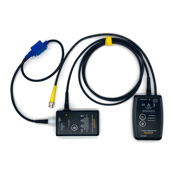
- Page 2 DIMENSIONS INTRODUCTION The HVCP from is a novel Rogowski current probe that provides high voltage isolation via fiber optic cables. Not only is this approach advantageous from the voltage isolation point of view but is also immune to typical radiated interferences and capacitances created when using long coaxial measuring cables.
-
Page 3: Safety Notes
It is always recommended that the probe head be installed over a tripod mount and secured When manually positioning the probe head keep in mind the unit is physically joined to the receiver unit, moving the probe head may send the receiver into the floor www.saker-mv.com BR-HVCP-0424-r1 Specifications subject to change without notice... -
Page 4: Specifications
SPECIFICATIONS HVCP Specification Units Bandwidth, rise time derived 5Hz…1MHz Output ratio 20 (HVCP100), 8 (HVCP250) mV/A 4 (HVCP500), 2 (HVCP1000) 1 (HVCP2000) Maximum measurable current 150 (HVCP100), 375 (HVCP250) 750 (HVCP500), 1500 (HVCP1000) 3000 (HVCP2000) ± Overall accuracy Delay for 2m version (0.009º... - Page 5 For available accessories refer to the published document for the HVCP probe. COMPATIBILITY The HVCP probe requires an external oscilloscope, digital multimeter, power analyzer or a recording device. In case an oscilloscope is used the bandwidth of the channel should be limited to 20MHz to avoid excess noise in the measurement.
-
Page 6: Installation And Use
Connect the receiver to an USB power supply using the supplied cable (USB A to USB micro cable). Set the oscilloscope vertical scale at an appropriate scale given the conversion ratio of www.saker-mv.com BR-HVCP-0424-r1 Specifications subject to change without notice... - Page 7 HVCP which is specified at the back of the receiver and in the specifications section. For Ω scopes the inputs must be set to 1M . The preferred method of operation is as follows: 1. Place and secure the probe head 2.
-
Page 8: Operation
TURN ON button until the ON Led lights. It takes a short press to turn on the units. If the probe head fails to turn on check if the batteries are dead, and replace them. The probe head cannot be turned on remotely. www.saker-mv.com BR-HVCP-0424-r1 Specifications subject to change without notice... - Page 9 Since the probe head can be set into low power mode remotely from the receiver, potentially dangerous situations where the measured system is floating at high voltage, are avoided. www.saker-mv.com BR-HVCP-0424-r1 Specifications subject to change without notice...
- Page 10 A short blink from the CAL led indicates that calibration is required. To execute calibration, first turn on both units and then shortly press the CAL button. The CAL led will turn on. If for some www.saker-mv.com BR-HVCP-0424-r1 Specifications subject to change without notice...
-
Page 11: Care And Maintenance
Due to their non-conductive nature, the fiber optic cables provide excellent isolation between probe head and receiver. However the probe head can and should be considered floating at the same potential of the measured conductor. Thus the whole body of the HVCP probe head can be at hazardous potentials. -
Page 12: Ordering Codes
Up to 15m can be configured PERFORMANCE VERIFICATION HVCP probes are shipped from Saker and both probe head and receiver are tested as a system and adjusted to meet the AC current accuracy and frequency specifications. Accuracy between emitter and receiver is automatically maintained by two internal precision voltage references and a software algorithm. - Page 13 CERTIFICATIONS The HVCP probe complies with EC Directive 2014/30/EU for Electromagnetic Compatibility. Compliance was demonstrated to the following specifications as listed in the Official Journal of the European Communities: EC/EN 61326-1:2021 EMC requirements for electrical equipment for measurement, control, and laboratory use: Electromagnetic Emissions: IEC/EN 55011/A1:2016 Radiated Emissions 30-1000 MHz.
Need help?
Do you have a question about the HVCP and is the answer not in the manual?
Questions and answers