
Related Manuals for Saker XFVP-L


Summary of Contents for Saker XFVP-L
- Page 1 User Manual XFVP-L Medium Voltage Fiber Isolated Voltage Probe Revision 2 www.saker-mv.com BR-XFVPL-Rev 2. 12/22...
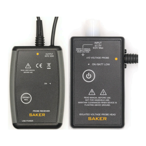
- Page 2 DIMENSIONS INTRODUCTION The XFVP-L is a novel voltage probe that provides high voltage isolation via fiber optic cables. Not only is this approach advantageous from the voltage isolation point of view, but is also immune to typical radiated interferences and capacitances created when using long coaxial measuring cables.
- Page 3 It is always recommended that the probe head be installed over a tripod mount and secured When manually positioning the probe head keep in mind the unit is physically joined to the receiver unit, moving the probe head may send the receiver into the floor www.saker-mv.com BR-XFVPL-Rev 2. 12/22...
- Page 4 SPECIFICATIONS XFVP-L Specification Units Bandwidth, minimum. (1)(2) >220 250 typ. Input impedance 1MΩ 0.5% || 8 pF ± Risetime, typical (1) Input voltage range ± Max voltage at input 500Vdc Noise, output referred <3 mVrms Delay, 2m cable. 5ns for each extra...
- Page 5 ACCESSORIES Several accessories for the XFVP-L are available which include patch cables, attenuators and external power supplies. Consult the accessories list. COMPATIBILITY The XFVP-L probe requires an external oscilloscope with internal 50 termination. The Ω termination is needed to provide appropriate high-frequency transmission of the signal. If the oscilloscope does not have internal 50 Ω...
- Page 6 CAT rated for use on these types of circuits according to definitions of IEC/EN 61010-031. The accessories provided by Saker for connecting the probe head to the DUT are compatible with the touch protected SMB connector in the probe. Please refer to the accessories list.
- Page 7 Set the oscilloscope vertical scale at an appropriate scale given the conversion ratio of the XFVP-L and attenuator (see specifications section) in question. A 50 Ω termination is necessary for calibration and signal integrity. The preferred method of operation is as follows: 1.
- Page 8 (for example the GEVP-OSC oscillator) in the range permitted by the attenuator and adjust the amplitude of the signal seen in the oscilloscope with the trimmer. www.saker-mv.com BR-XFVPL-Rev 2. 12/22...
- Page 9 Due to their non-conductive nature, fiber optic cables provide excellent isolation between probe head and receiver. However the probe head is floating at the same potential of the measured conductor. Thus the whole body of the XFVP-L probe head can be at hazardous potentials.
- Page 10 1m USB cable. Specify -x for length, standard PERFORMANCE VERIFICATION XFVP-L probes are shipped from Saker and both probe head and receiver are tested as a system and adjusted to meet the DC gain, offset and bandwidth specification.
- Page 11 Press the ON key on the emitter and check that it turns off. Connect the XFVP-L in a setup as shown below. Install new alkaline batteries in the transmitter. Turn on the probe head and receiver and wait 5 minutes before starting the tests.
- Page 12 2V as possible (within 10mV max). 3) Connect the voltage source to the probe head with the BNC/SMB adapter. 4) Connect the output of the XFVP-L to the multimeter using the 50 Ohm terminator and the BNC to jack adapter 5) Press the CAL button in the XFVP receiver.
- Page 13 7. The average level should be about -20dBm (x10 attenuation). Find the -23dBm frequency. CERTIFICATIONS The XFVP-L probe complies with EC Directive 2014/30/EU for Electromagnetic Compatibility. Compliance was demonstrated to the following specifications as listed in the Official Journal of...
Need help?
Do you have a question about the XFVP-L and is the answer not in the manual?
Questions and answers