
Related Manuals for Saker XFVP


Summary of Contents for Saker XFVP
- Page 1 User Manual XFVP Medium Voltage Fiber Isolated Voltage Probe Revision 5 www.saker-mv.com BR-XFVP-Rev 5.
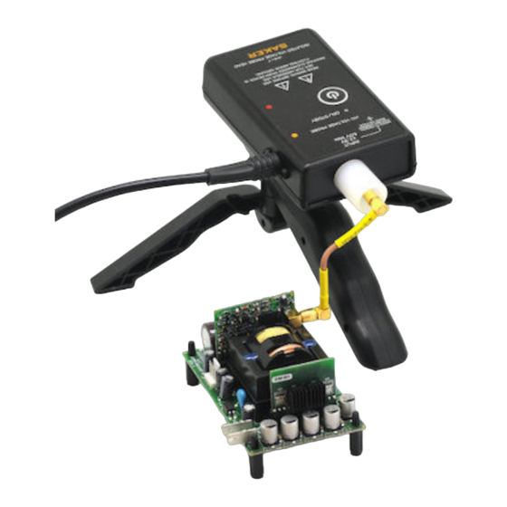
- Page 2 DIMENSIONS INTRODUCTION The XFVP probe is a novel voltage probe that provides high voltage isolation via fiber optic cables. Not only is this approach advantageous from the voltage isolation point of view, but is also immune to typical radiated interferences and capacitances created when using long coaxial measuring cables.
- Page 3 It is always recommended that the probe head be installed over a tripod mount and secured When manually positioning the probe head keep in mind the unit is physically joined to the receiver unit, moving the probe head may send the receiver into the floor www.saker-mv.com BR-XFVP-Rev 5.
- Page 4 SPECIFICATIONS XFVP Specification Units Bandwidth (1)(2) 75, 175 ± Input impedance 1MΩ 0.5% || 8 pF Risetime, typical (1) <5, <2.5 ± Input voltage range Max voltage at input 500Vdc Noise, output referred <3 mVrms Delay, 2m cable Offset error, output referred, after cal <1...
- Page 5 External patch cables that interface the user system with the SMB connector can be made by the user. Saker recommends the use of good quality SMB connectors, for example reference R114082000 from Radiall. Please read the accessories PDF to find more about these. The unterminated SMB cable leaves freedom of choice for the user to make additional terminations.
- Page 6 Set the oscilloscope vertical scale at an appropriate scale given the conversion ratio of the Ω XFVP and attenuator (see specifications section) in question. A 50 termination is necessary for calibration to take place successfully.
- Page 7 6. Power on the DUT. When the oscilloscope and DUT are ready, take the XFVP probe out of the standby mode by shortly pressing the ON/OFF button and the press the CAL button. 7. Take measurements as needed. During interpretation of results or during adjustments to the DUT place the probe in standby again.
- Page 8 To enter standby mode, press the TURN ON button shortly in either unit. The ON green led will start blinking. The other unit will also enter low power mode. www.saker-mv.com BR-XFVP-Rev 5.
- Page 9 CAL button. The CAL led will turn on. If for some Ω reason both units cannot communicate or the scope is not 50 terminated, the CAL led will www.saker-mv.com BR-XFVP-Rev 5.
- Page 10 It is advisable to install a voltage detector/indicator on the measured line that provides visual and clear indication about the presence of potentially dangerous voltages. SAKER offers the MVD and MVDZ series of medium voltage presence detectors. LOW BATTERY CONDITION The probe head will measure the voltage of the batteries to warn the user in case of a low battery condition.
- Page 11 EQUIPMENT CODES CODE Description XFVP20-2 XFVP probe 175MHz with 1m output BNC cable, SMB unterminated cable, x10 attenuator, 2xAA batteries, tripod, quick guide, case, USB cable. Fiber cable 2m in length available up to 15m XFVP10-x Same as XFVP20-2 probe but 75MHz BW www.saker-mv.com...
- Page 12 PERFORMANCE VERIFICATION XFVP probes are shipped from Saker and both probe head and receiver are tested as a system and adjusted to meet the DC gain, offset and frequency specifications. Accuracy is automatically maintained by two internal precision voltage references and a software algorithm so there is no provision for manual user adjustment.
- Page 13 2) Measure the voltage of the voltage source with the multimeter in the mV scale. 3) Connect the voltage source to the probe head with the BNC/SMB adapter. 4) Connect the output of the XFVP to the multimeter using the 50Ohm terminator and the BNC to jack adapter.
- Page 14 2V as possible (within 10mV max). 3) Connect the voltage source to the probe head with the BNC/SMB adapter. 4) Connect the output of the XFVP to the multimeter using the 50 Ohm terminator and the BNC to jack adapter 5) Press the CAL button in the XFVP receiver.
- Page 15 The XFVP probe complies with EC Directive 2014/30/EU for Electromagnetic Compatibility. Compliance was demonstrated to the following specifications as listed in the Official Journal of the European Communities: EC/EN 61326-1:2013 EMC requirements for electrical equipment for measurement, control, and laboratory use: Electromagnetic Emissions: IEC/EN 55011/A1:2011 Radiated Emissions 30-1000 MHz.
Need help?
Do you have a question about the XFVP and is the answer not in the manual?
Questions and answers