
Related Manuals for Saker XFVP10-2


Summary of Contents for Saker XFVP10-2
- Page 1 User Manual XFVP Medium Voltage Fiber Isolated Voltage Probe Revision 6 www.saker-mv.com BR-XFVP-Rev 6. 12/22...
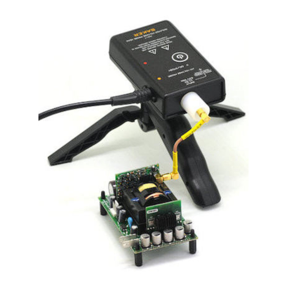
- Page 2 Lastly the back of the probe head features a standard camera tripod mount thread. This makes it more convenient to place the probe inside tightly spaced cabinets or power modules and maintain proper clearance distances. www.saker-mv.com BR-XFVP-Rev 6. 12/22...
- Page 3 It is always recommended that the probe head be installed over a tripod mount and secured When manually positioning the probe head keep in mind the unit is physically joined to the receiver unit, moving the probe head may send the receiver into the floor www.saker-mv.com BR-XFVP-Rev 6. 12/22...
- Page 4 2) -3dB, small signal, 25Ω source 3) See user manual for more details CE certification GPSD 2001/95/EC, 4) Normalized to 1V input range ± EMC Directive 5) Zero and gain cal 2014/30/EU, 6) Tested with alkaline or 2600mAh NiMh RoHS2 2011/65/EU www.saker-mv.com BR-XFVP-Rev 6. 12/22...
- Page 5 External patch cables that interface the user system with the SMB connector can be made by the user. Saker recommends the use of good quality SMB connectors, for example reference R114082000 from Radiall. Please read the accessories PDF to find more about these. The unterminated SMB cable leaves freedom of choice for the user to make additional terminations.
- Page 6 5. Place the unit in standby mode by shortly pressing the ON/OFF button. From this moment there is no need to approach the probe head, since it can be turned on from the receiver. Calibration also can take place while the DUT is energized. www.saker-mv.com BR-XFVP-Rev 6. 12/22...
- Page 7 The probe head can be turned off in two ways. Either directly by pressing the TURN ON button for 1 second or remotely by turning off the receiver. In either case the ON led will turn off. www.saker-mv.com BR-XFVP-Rev 6. 12/22...
- Page 8 To enter standby mode, press the TURN ON button shortly in either unit. The ON green led will start blinking. The other unit will also enter low power mode. www.saker-mv.com BR-XFVP-Rev 6. 12/22...
- Page 9 CAL button. The CAL led will turn on. If for some reason both units cannot communicate or the scope is not 50 Ω terminated, the CAL led will www.saker-mv.com BR-XFVP-Rev 6. 12/22...
- Page 10 It is advisable to install a voltage detector/indicator on the measured line that provides visual and clear indication about the presence of potentially dangerous voltages. SAKER offers the MVD and MVDZ series of medium voltage presence detectors. LOW BATTERY CONDITION The probe head will measure the voltage of the batteries to warn the user in case of a low battery condition.
- Page 11 XFVP probe 220MHz with 0.5m output BNC cable, SMB unterminated cable, x10 attenuator, 2xAA batteries, tripod, quick guide, case, USB cable. Fiber cable 2m in length available up to 15m XFVP10-x Same as XFVP20-2 probe but 110MHz BW www.saker-mv.com BR-XFVP-Rev 6. 12/22...
- Page 12 PERFORMANCE VERIFICATION XFVP probes are shipped from Saker and both probe head and receiver are tested as a system and adjusted to meet the DC gain, offset and frequency specifications. Accuracy is automatically maintained by two internal precision voltage references and a software algorithm so there is no provision for manual user adjustment.
- Page 13 5) Press the CAL button in the XFVP receiver. 6) The offset is the difference between the voltage measured at the voltage source and the voltage measured at the output of the XFVP probe * 10. www.saker-mv.com BR-XFVP-Rev 6. 12/22...
- Page 14 AC coupling. 7. Remove this external termination and connect the output of the XFVP probe to the input of the spectrum analyzer. The average level should be about -20dBm (x10 attenuation). Find the -23dBm frequency. CERTIFICATIONS www.saker-mv.com BR-XFVP-Rev 6. 12/22...
- Page 15 1400 MHz - 2700 MHz; 3 V/m, 2 GHz - 2.7 GHz For safety compliance the product meets the IEC 61010-1 2017 Ed. and General Product Safety Directive GPSD 2001/95/EC. The product and its accessories conform to the 2011/65/EU RoHS2 Directive. DIMENSIONS www.saker-mv.com BR-XFVP-Rev 6. 12/22...
Need help?
Do you have a question about the XFVP10-2 and is the answer not in the manual?
Questions and answers