
Subscribe to Our Youtube Channel
Related Manuals for Lincoln Electric CITOTIG 315 AC/DC


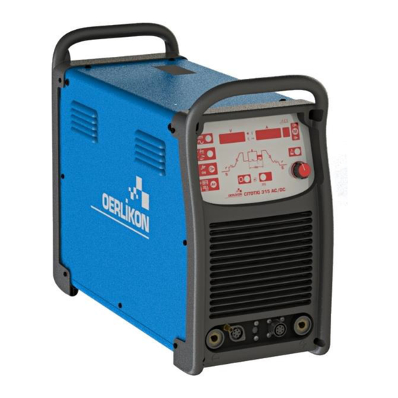
Summary of Contents for Lincoln Electric CITOTIG 315 AC/DC
- Page 1 SVM 3086 Rev.00 03-2019 CITOTIG 315 AC/DC For use with machines having code numbers: 50406 LINCOLN ELECTRIC EUROPE www.lincolnelectric.eu...
-
Page 2: Table Of Contents
INDEX OF CONTENTS INDEX OF CONTENTS ............................2 TECHNICAL SPECIFICATIONS AND ACCESSORIES ................... 3 SAFETY ................................4 INSTALLATION AND OPERATOR INSTRUCTIONS ..................5 MAINTENANCE ............................... 23 MAJOR COMPONENTS LOCATION ......................25 THEORY OF OPERATION ..........................26 INPUT ................................27 INVERTER-OUTPUT TRANSFORMER AND OUTPUT DIODE PCB............. 28 OUTPUT BOARD, IGBT BOARD AND HF BOARD .................. -
Page 3: Technical Specifications And Accessories
TECHNICAL SPECIFICATIONS AND ACCESSORIES CITOTIG 315 AC/DC INPUT Input Voltage U EMC Class Frequency 230 - 400Vac ± 15% 50/60 Hz Input Line Mode 100% Input Amperes I PFmax 1max STICK 10.3kW 8.8 kW TIG DC 8.8kW 6.4 kW 4.8kW 230Vac 27.4 A... -
Page 4: Safety
Failure to follow the instructions in this manual could cause serious personal injury, loss of life, or damage to this equipment. Read and understand the following explanations of the warning symbols. Lincoln Electric is not responsible for damages caused by improper installation, improper care or abnormal operation. -
Page 5: Installation And Operator Instructions
Locate the machine away from radio controlled General description • machinery. Normal operation may adversely CITOTIG 315 AC/DC machine is designated to performe affect the operation of nearby radio controlled SMAW and GTAW welding process in DC and AC machinery, which may result in injury or current. - Page 6 It is important to check these conditions because many engine driven generators produce high voltage spikes. Connect the torch cable Operation of this machine on engine driven generators to the torch terminal of not conforming to these conditions is not recommended the machine and the and may damage the machine.
- Page 7 Rear Panel Controls and Operational Features Power Switch: It turns Machine Start-Up: ON / OFF the input When the machine is turned ON an auto-test is power to the machine. executed. The Machine is ready to operate when on the Front Input cable: Connect Control Panel lights up the “Power ON”...
- Page 8 Process: Connecting the Remote command excludes the Output Current Knob of the Machine’s user interface. Through the Remote command is available the full Output Current Range. TIG mode: in Local and remote mode the • output of the machine is OFF. A Trigger is necessary to enable the output.
- Page 9 To enable Expert mode: Pre-Flow: Sets the time in Push the AC WAVESHAPE button twice: The AUTO seconds gas will flow prior to icon will start to blink and the display will show the arc-start initiation message AUTO ON. Turn the encoder to select AUTO OFF Confirm the selection by pushing the AC WAVESHAPE button again.
- Page 10 Main Amperage Control: Saving Memory Settings: In order to save process settings into a memory location it is first necessary to press the memory button so that the “memory save” icon is highlighted. Once highlighted, the number on the screen will flash to indicate this number can be changed by turning the control knob below, and the voltage and amperage meters will say “MEM SET”.
- Page 11 Auto Adaptive Arc Force: this function increases Menu: temporary the output current, used to clear intermittent connections between the electrode and the weld puddle that occur during stick welding. This is an active control feature that guarantees the best arrangement between the arc stability and spatter presence.
- Page 12 GTAW welding Tig Welding Sequences DC TIG Welding To start DC Tig welding process: During no welding operation at each pressure of SEL push button, it’s possible to step through all sequencer 5.) Set polarity and set parameters. 6.) To select TIG welding: Process Visualization During welding the Sel pushbutton is enabled for the...
- Page 13 Press and hold the TIG torch trigger to start the sequence. The machine will open the gas valve to start the flow of the shielding gas. After the preflow time, to purge air from the torch hose, the output of the machine is turned ON.
- Page 14 Press and hold the TIG torch trigger. The machine If the Start current is not necessary, do not hold the will now decrease the output current at a controlled TIG torch trigger as described at the beginning of rate, or downslope time, until the Crater current is this step.
- Page 15 To set the A2 level, user has to push SEL button until This welding mode is especially thought to tack or weld text A2 appears on the left display: turning now the main thin materials. know is possible to set A2 in percentage of the setting It uses HF start and immediately It delivers the set current.
- Page 16 List of parameters and Factory stored programs Displayed Displayed parameter name value Selectable Value Range Function Factory Configuration Default Current Preflow 0 - 25s (step 0.1s) selected value Current STRT Starting Current 10 – 200 % (step 1%) selected value Current Initial slope 0 –...
- Page 17 Advanced menu Menu GTAW To enter into Menu GTAW see section Menu, described above Menu GTAW Displayed Displayed parameter value name Selectable Value Range Function Factory Configuration Default SOFT Current SINE WAVE Wave Form SQRE selected value SQRE type AUTO (Note D) 0.5mm (0.02”) 1mm (0.04”) 1.6mm (1/16”)
- Page 18 Note D. When AUTO is selected, the starting parameters are automatically recalled based on the set current adjustable by main knob in the front panel. Diameter of the electrode is automatically recalled based on the following table User dialed weld I (AMP) Tungsten diameter >...
- Page 19 Menu SMAW To enter into Menu SMAW see section Menu, descriped above Menu SMAW Displayed Displayed parameter value name Selectable Value Range Function Factory Configuration Default SOFT: 35% 0 – 75% (step 1%) Current FRCE Arc Force selected value CRISP: 75% 75 –...
- Page 20 Menu SYS To enter into Menu SYS see section Menu, descriped above Menu SYS Displayed Displayed parameter name value Selectable Value Range Function Factory Configuration Default Current UNIT Units mm / INCH selected value ON/OFF Brightness/Intensity HIGH FOOT Current RMTE TIG Remote Options selected value type...
- Page 21 LED Brightness/Intensity Error Codes and troubleshooting. By this option is possible to select the intensity of the LEDs present in the user interface: three level can be If an error occurs, turn Off the machine, wait for a few selected by the user. High level is reccomended when seconds, then turn ON again.
- Page 22 Arc Time & Arc Counter These two options show to the welder the total working hours and the total numeber of arc striking. To reset one or both register, performe the follow procedure: Select the option to reset; Push SEL button for 5s.
-
Page 23: Maintenance
MAINTENANCE WARNING INPUT DC BUS CAPACITORS DISCHARGE PROCEDURE Remove input power to the CITOTIG 315 AC/DC ELECTRIC SHOCK can kill Remove the cover following the instruction available in this Service manual. Have an electrician install and service this equipment Check the voltage across the two terminals. Voltage Turn the input power off at the fuse box before working on should be zero. - Page 24 ROUTINE MAINTENANCE THERMAL PROTECTION Keep the welding area around the machine clean and Thermal detection device protect the machine from free of combustible materials. No debris should be excessive operating temperatures. Excessive temperatures allowed to collect which could obstruct air flow to the may be caused by a lack of cooling air or operating the machine machine beyond the duty cycle and output rating.
-
Page 25: Major Components Location
MAJOR COMPONENTS LOCATION CITOTIG 315 AC/DC 1. Mains switch 7. IGBT Board 2. Gas solenoid valve 8. HF Board 3. Fan and Fan1 9. Input control Board 4. Right side:Buck/Boost Board, Caps Board and 10. Input Power Board Inverter Board 11. -
Page 26: Theory Of Operation
THEORY OF OPERATION CITOTIG 315 AC/DC - SCHEMATIC DIAGRAM code 50406... -
Page 27: Input
INPUT GENERAL DESCRIPTION Buck/Boost Power Board. The Buck/Boost Power The CITOTIG 315 AC/DC is an inverter based welding Board houses a soft-start circuit consisting of a 100 power source that offers multi-mode (TIG DC, TIG AC ohm resistor and a DC relay. Initially the DC relay is STICK DC and STICK AC) constant current welding. -
Page 28: Inverter-Output Transformer And Output Diode Pcb
INVERTER-OUTPUT TRANSFORMER AND OUTPUT DIODE PCB INVERTER, OUTPUT TRANSFORMER AND OUTPUT DIODE PCB The 400VDC created by the Buck/Boost Board and The main transformer insulate the primary circuit from filtered by the DC bus capacitors is applied to an IGBT the secondary circuit and reduces the high voltage controlled full wave bridge inverter that is located on (low current) input applied to the primary winding and... -
Page 29: Output Board, Igbt Board And Hf Board
OUTPUT BOARD, IGBT BOARD AND HF BOARD OUTPUT BOARD, IGBT BOARD The OUTPUT board provides the managing signals output of the machine can be either DC positive, DC and the insulated power supply for the driver of the negative or AC. Output IGBT module. -
Page 30: Control And User Interface Board
CONTROL AND USER INTERFACE BOARD CONTROL AND USER INTERFACE BOARD To generate the wished DC waveform ( like, pulse , The User Interface board houses the control panel, upslope, downslope,…). LEDs, push buttons, encoder and functions as the Control Board and User interface communicate via interface between the user and the CITOTIG 315 serial bus. - Page 31 OVERLOAD PROTECTION cooling air or by operating the machine beyond the duty cycle and output rating. If excessive operating CITOTIG 315 AC/DC is electrically protected from temperature should occur, the Thermal LED indicator producing higher than normal output currents. An...
- Page 32 INSULATED GATE BIPOLAR TRANSISTOR (IGBT) Drawing B shows the IGBT in an active mode. OPERATION When the gate signal, a positive DC voltage relative to the source, is applied to the gate An IGBT is a type of transistor. IGBTs are terminal of the IGBT, it is capable of conducting semicon-ductors well suited for high frequency current.
-
Page 33: Troubleshooting And Repair Section
TROUBLESHOOTING AND REPAIR SECTION How to use troubleshooting Guide Troubleshooting Guide Case cover removal and capacitor discharge procedure EMC Filter Board test Input Rectifier test Buck/Boost Board test Input Power board test Input Control board test ... - Page 34 HOW TO USE TROUBLESHOOTING GUIDE Service and repair should be performed by only Lincoln Electric Factory Trained Personnel. Unauthorized repairs performed on this equipment may result in danger to the technician and machine operator and will invalidate your factory warranty. For your safety and to avoid Electrical Shock, please observe all safety notes and precautions detailed throughout this manual.
- Page 35 WARNING NOTE: Allow the machine to heat up so that all electrical components can reach their operating temperature. 5. Remove the replacement PC board and ELECTRIC SHOCK can kill substitute it with the original PC board to recreate the original problem. Have an electrician install and service this •...
- Page 36 TESTS* CONTROL BOARD This tests and repair should only be performed by Lincoln Electric Trained Personnel. Unauthorized repairs performed on this equipment may result in danger to the technician and machine operator and will invalidate your factory warranty. For your safety and to avoid Electrical Shock, please observe all safety notes and precautions detailed throughout this...
-
Page 37: Case Cover Removal And Dc Bus Capacitor Discharge Procedure
DISCHARGE PROCEDURE WARNING Service and repair should be performed only by Lincoln Electric factory trained personnel.Unauthorized repairs performed on this equipment may result in danger to the technician or machine operator and will invalidate your factory warranty. For your safety and to avoid electrical shock, please observe all safety notes and precautions detailed throughout this manual. - Page 38 CITOTIG 315 AC/DC - CASE COVER REMOVAL Procedure: 1. Turn ON/OFF switch to OFF position. 2. Disconnect Input Power from the machine ! 3. Remove the 4 screws of the front plastic panel and 4 from the rear plastic panel (A) 4.
- Page 39 DC BUS CAPACITORS DISCHARGE PROCEDURE WARNING INPUT DC BUS CAPACITORS DISCHARGE PROCEDURE Remove input power to the CITOTIG 315 AC/DC ELECTRIC SHOCK can kill Remove the cover following the instruction available in this Service manual. Have an electrician install and service this equipment Check the voltage across the two terminals.
-
Page 40: Emc Filter Board Test
EMC FILTER BOARD TEST WARNING Service and repair should be performed by only Lincoln Electric factory trained personnel. Unauthorized repairs performed on this equipment may result in danger to the technician or machine operator and will invalidate your factory warranty. For your safety and to avoid electrical shock, please observe all safety notes and precautions detailed throughout this manual. - Page 41 TEST PROCEDURE Use always electrically insulate gloves during this test procedure 1. Remove main input power to the CITOTIG 315 AC/DC 2. Perform the Case removal and Discharge procedure 3. Locate the EMC Filter Board W05X1547 (see major components location available in this manual).
-
Page 42: Input Rectifier Test
INPUT RECTIFIER TEST WARNING Service and repair should be performed by only Lincoln Electric factory trained personnel. Unauthorized repairs performed on this equipment may result in danger to the technician or machine operator and will invalidate your factory warranty. For your safety and to avoid electrical shock, please observe all safety notes and precautions detailed throughout this manual. - Page 43 TEST PROCEDURE Use always electrically insulate gloves during this test procedure 1. Remove main input power to the CITOTIG 315 AC/DC. 2. Perform the Case removal and Discharge procedure 3. Locate the Input Rectifier Bridge on the right side of the machine. See Figure 3.
-
Page 44: Buck/Boost Board Test
BUCK/BOOST BOARD TEST WARNING Service and repair should be performed by only Lincoln Electric factory trained personnel. Unauthorized repairs performed on this equipment may result in danger to the technician or machine operator and will invalidate your factory warranty. For your safety and to avoid electrical shock, please observe all safety notes and precautions detailed throughout this manual. - Page 45 BUCK/BOOST BOARD TEST (continued) BUCK/ BOOST Board Figure 4 – W05X0982 BUCK/BOOST Board location IND2 DCIN- R6, test point 1 IND1 DCIN+ R6, test point 2 Relay Coil – (D6) Figure 5 – W05X0982 BUCK/BOOST Board Test points...
- Page 46 TEST PROCEDURE Use always electrically insulate gloves during this test procedure 1. Remove main input power to the CITOTIG 315 AC/DC. 2. Perform the Case removal and Discharge procedure 3. Locate the Buck/Boost board on the right side of the machine. See Figure 4.
-
Page 47: Input Power Board Test
INPUT POWER BOARD TEST WARNING Service and repair should be performed by only Lincoln Electric factory trained personnel. Unauthorized repairs performed on this equipment may result in danger to the technician or machine operator and will invalidate your factory warranty. For your safety and to avoid electrical shock, please observe all safety notes and precautions detailed throughout this manual. - Page 48 INPUT POWER BOARD TEST (continued) INPUT POWER Board Figure 6 – W05X1461 INPUT POWER Board location JIP4 JIP1 JIP3 JIP6 JIP5 JIP2 JIP7 Figure 7 – W05X1461 INPUT POWER Board Test Points...
- Page 49 4. Visually check for burned or damaged components. If any components are physically damaged the Input Power board should be replaced 5. Carefully apply 400Vac-3ph +/-15% or 230Vac-3ph +/-15% via the input cable to the CITOTIG 315 AC/DC, switch ON the machine and wait till the power LED on front panel is steady green.
-
Page 50: Input Control Board Test
INPUT CONTROL BOARD TEST WARNING Service and repair should be performed by only Lincoln Electric factory trained personnel. Unauthorized repairs performed on this equipment may result in danger to the technician or machine operator and will invalidate your factory warranty. For your safety and to avoid electrical shock, please observe all safety notes and precautions detailed throughout this manual. - Page 51 INPUT CONTROL BOARD TEST (continued) INPUT CONTROL Board Figure 8 – W05X1460 INPUT CONTROL Board location JIP_S JIP_W JIP_P Figure 9 – W05X1460 INPUT CONTROL Board Test Points...
- Page 52 4. Visually check for burned or damaged components. If any components are physically damaged the Input Control board should be replaced 5. Carefully apply 400Vac/3ph +/-15% or 230Vac-3ph +/-15% via the input cable to the CITOTIG 315 AC/DC, switch ON the machine and wait till the power LED on front panel is steady green.
- Page 53 OFF single phase is detected 230Vac flashing Indicates the machine is supplied at 230Vac green 400Vac or LD3 OFF LD3 blinking= overvoltage condition 230Vac Dip Switch bank - DS1 = For CITOTIG 315 AC/DC European Version all dip switches must be in OFF position...
-
Page 54: Inverter Board Resistance Test
INVERTER BOARD RESISTANCE TEST WARNING Service and repair should be performed by only Lincoln Electric factory trained personnel. Unauthorized repairs performed on this equipment may result in danger to the technician or machine operator and will invalidate your factory warranty. For your safety and to avoid electrical shock, please observe all safety notes and precautions detailed throughout this manual. - Page 55 Figure 10 – W05X1327-3 INVERTER Board Test Points TEST PROCEDURE 1. Remove main input power to the CITOTIG 315 AC/DC 2. Perform the Case removal and Discharge procedure 3. Visually check for burned or damaged components. If any components are physically damaged the inverter board and damaged components should be replaced.
-
Page 56: Inverter Board Voltage Test
INVERTER BOARD VOLTAGE TEST WARNING Service and repair should be performed by only Lincoln Electric factory trained personnel. Unauthorized repairs performed on this equipment may result in danger to the technician or machine operator and will invalidate your factory warranty. For your safety and to avoid electrical shock, please observe all safety notes and precautions detailed throughout this manual. - Page 57 Use always electrically insulate gloves during this test procedure 1. Carefully apply 400Vac +/- 15% or 230Vac-3ph +/-15% to the CITOTIG 315 AC/DC 2. Turn the machine input switch to ON position, and wait till the power LED on front panel is steady green.
-
Page 58: Output Board Test
OUTPUT BOARD TEST WARNING Service and repair should be performed by only Lincoln Electric factory trained personnel. Unauthorized repairs performed on this equipment may result in danger to the technician or machine operator and will invalidate your factory warranty. For your safety and to avoid electrical shock, please observe all safety notes and precautions detailed throughout this manual. - Page 59 TEST PROCEDURE Use always electrically insulate gloves during this test procedure 1. Remove main input power to the CITOTIG 315 AC/DC 2. Perform the Case removal and Discharge procedure 3. Locate the Output board on the left side of the machine. See Figure 12.
- Page 60 OUTPUT BOARD TEST (continued) 6. Carefully apply 400Vac +/- 15% or 230Vac-3ph +/-15% to the CITOTIG 315 AC/DC 7. Turn the machine input switch to ON position, and wait till the power LED on front panel is steady green. 8. Perform the tests detailed in Test Table 10. See Figure 13 for Test Point locations: Test table 10 –...
-
Page 61: Output Diode Board Resistance Test
OUTPUT DIODE BOARD RESISTANCE TEST WARNING Service and repair should be performed by only Lincoln Electric factory trained personnel. Unauthorized repairs performed on this equipment may result in danger to the technician or machine operator and will invalidate your factory warranty. For your safety and to avoid electrical shock, please observe all safety notes and precautions detailed throughout this manual. - Page 62 OUTPUT DIODE BOARD RESISTANCE TEST (continued) OUTPUT DIODE Board Figure 14 – W05X1523 OUTPUT DIODE board location Figure 15 – W05X1523 OUTPUT DIODE board test points...
- Page 63 TEST PROCEDURE Use always electrically insulate gloves during this test procedure 1. Remove main input power to the CITOTIG 315 AC/DC 2. Perform the Case removal and Discharge procedure 3. Locate the Output Diode board on the left side of the machine. See Figure 14.
-
Page 64: Igbt Board Resistance Test
IGBT BOARD RESISTANCE TEST WARNING Service and repair should be performed by only Lincoln Electric factory trained personnel. Unauthorized repairs performed on this equipment may result in danger to the technician or machine operator and will invalidate your factory warranty. For your safety and to avoid electrical shock, please observe all safety notes and precautions detailed throughout this manual. - Page 65 IGBT BOARD RESISTANCE TEST (continued) IGBT Board Figure 16 – W05X1524 IGBT board location E1/C2 Figure 17 – W05X1524 IGBT board test points...
- Page 66 TEST PROCEDURE Use always electrically insulate gloves during this test procedure 1. Remove main input power to the CITOTIG 315 AC/DC 2. Perform the Case removal and Discharge procedure 3. Locate the IGBT board on the left side of the machine. See Figure 16.
-
Page 67: Hf Board Test
HF BOARD TEST WARNING Service and repair should be performed by only Lincoln Electric factory trained personnel. Unauthorized repairs performed on this equipment may result in danger to the technician or machine operator and will invalidate your factory warranty. For your safety and to avoid electrical shock, please observe all safety notes and precautions detailed throughout this manual. - Page 68 HF BOARD TEST (continued) HF Board Figure 18 – W05X1615 HF board location HV-RTN to Input (to the HF transformer) (to the HF transformer) Diode D9 control Board Figure 19 – W05X1615 HF board test points...
- Page 69 Use always electrically insulate gloves during this test procedure 1. Carefully apply 400Vac +/- 15% or 230Vac-3ph +/-15% to the CITOTIG 315 AC/DC 2. Turn the machine input switch to ON position and wait till the power LED on front panel is steady green.
-
Page 70: Control Board And User Interface Test
CONTROL BOARD AND USER INTERFACE TEST WARNING Service and repair should be performed by only Lincoln Electric factory trained personnel. Unauthorized repairs performed on this equipment may result in danger to the technician or machine operator and will invalidate your factory warranty. - Page 71 CONTROL BOARD AND USER INTERFACE TEST (continued) Control and User Interface Boards Figure 20 – W05X1648 and W05X1649 Control and User Interface boards location to remote connector to torch trigger connector used Figure 21 – W05X1648 CONTROL boards test points Pin9 Pin10 Pin1...
- Page 72 4. Visually check for burned or damaged components. If any components are physically damaged the Control or UI board should be replaced 5. Carefully apply 400Vac/3ph +/-15% or 230Vac-3ph +/-15% via the input cable to the CITOTIG 315 AC/DC and switch ON the machine and wait till the power LED on front panel is steady green.
-
Page 73: Gas Solenoid Test
GAS SOLENOID TEST WARNING Service and repair should be performed by only Lincoln Electric factory trained personnel. Unauthorized repairs performed on this equipment may result in danger to the technician or machine operator and will invalidate your factory warranty. For your safety and to avoid electrical shock, please observe all safety notes and precautions detailed throughout this manual. - Page 74 Use always electrically insulate gloves during this test procedure 1. Carefully apply 400Vac +/- 15% or 230Vac-3ph +/-15% to the CITOTIG 315 AC/DC 2. Turn the machine input switch to ON position, and wait till the power LED on front panel is steady green.
-
Page 75: Disassembly Operations
Upon reassembly the same type and size screw and washers MUST be used. 1. Remove main input power to the CITOTIG 315 AC/DC. 2. Perform the Case Removal and Discharge procedure 3. Locate the EMC board W05X1471. See Figure 23 4. - Page 76 Torque wrench screw and washers MUST be used. 1. Remove main input power to the CITOTIG 315 AC/DC. 2. Perform the Case Removal and Discharge procedure 3. Locate the 3 phases input rectifier bridge W6814030 on the right side of the machine. See Figure24 4.
- Page 77 MUST be used. Torque wrench Silicon sealer 1. Remove main input power to the CITOTIG 315 AC/DC 2. Perform the Case Removal and Discharge procedure 3. Locate the Buck/Boost board W05X0982 on the right side of the machine, see Figure 25 4.
- Page 78 DISASSEMBLY OPERATIONS BUCK/BOOST BOARD REMOVAL AND REPLACEMENT PROCEDURE (continued) WARNING Disconnect input power before servicing. Do not operate with covers removed. Do not touch electrically live parts. Only qualified persons should install, use ELECTRIC SHOCK or service this equipment. CAN KILL Figure 26 7.
- Page 79 Torque wrench screw and washers MUST be used. 1. Remove main input power to the CITOTIG 315 AC/DC 2. Perform the Case Removal and Discharge procedure 3. Locate the Caps board W05X1470 on the right side of the machine, see Figure 27 4.
- Page 80 Dow Corning 340 Heat Sink Compound Silicon sealer 1. Remove main input power to the CITOTIG 315 AC/DC 2. Perform the Case Removal and Discharge procedure 3. Locate the Inverter board W05X1327-3 on the right side of the machine, see Figure 28 4.
- Page 81 DISASSEMBLY OPERATIONS INVERTER BOARD REMOVAL AND REPLACEMENT PROCEDURE (continued) WARNING Disconnect input power before servicing. Do not operate with covers removed. Do not touch electrically live parts. Only qualified persons should install, use ELECTRIC SHOCK or service this equipment. CAN KILL Figure 29 10.
- Page 82 Screwdriver type PH02 Torque wrench 1. Remove main input power to the CITOTIG 315 AC/DC 2. Perform the Case Removal and Discharge procedure 3. Locate the Input Power board W05X1461 on the upper left side of the machine, see Figure 30 4.
- Page 83 Screwdriver PH02 Torque wrench 1. Remove main input power to the CITOTIG 315 AC/DC 2. Perform the Case Removal and Discharge procedure 3. Locate the Input Control board W05X1460 on the upper right side of the machine, see Figure 31 4.
- Page 84 MUST be used. Torque wrench 1. Remove main input power to the CITOTIG 315 AC/DC 2. Perform the Case Removal and Discharge procedure 3. Locate the Output board W05X1527 on the left side of the machine, see Figure 32 4.
- Page 85 DISASSEMBLY OPERATIONS OUTPUT BOARD REMOVAL AND REPLACEMENT PROCEDURE (continued) WARNING Disconnect input power before servicing. Do not operate with covers removed. Do not touch electrically live parts. Only qualified persons should install, use ELECTRIC SHOCK or service this equipment. CAN KILL Figure 33 9.
- Page 86 Dow Corning 340 Heat Sink Compound Silicon sealer 1. Remove main input power to the CITOTIG 315 AC/DC 2. Perform the Case Removal and Discharge procedure 3. Locate the Output Diode board W05X1523 on the left side of the machine, see Figure 34 4.
- Page 87 DISASSEMBLY OPERATIONS OUTPUT DIODE PCB REMOVAL AND REPLACEMENT PROCEDURE (continued) WARNING Disconnect input power before servicing. Do not operate with covers removed. Do not touch electrically live parts. Only qualified persons should install, use ELECTRIC SHOCK or service this equipment. CAN KILL Figure 35 9.
- Page 88 Torque wrench Dow Corning 340 Heat Sink Compound 1. Remove main input power to the CITOTIG 315 AC/DC 2. Perform the Case Removal and Discharge procedure 3. Locate the IGBT board W05X1524 on the left side of the machine, see Figure 36 4.
- Page 89 DISASSEMBLY OPERATIONS IGBT PCB AND IGBT MODULE REMOVAL AND REPLACEMENT PROCEDURE (continued) WARNING Disconnect input power before servicing. Do not operate with covers removed. Do not touch electrically live parts. Only qualified persons should install, use ELECTRIC SHOCK or service this equipment. CAN KILL Figure 37 8.
- Page 90 DISASSEMBLY OPERATIONS IGBT PCB AND IGBT MODULE REMOVAL AND REPLACEMENT PROCEDURE (continued) WARNING Disconnect input power before servicing. Do not operate with covers removed. Do not touch electrically live parts. Only qualified persons should install, use ELECTRIC SHOCK or service this equipment. CAN KILL Flat Washer...
- Page 91 Allen wrench 2,5mm Small pliers 1. Remove main input power to the CITOTIG 315 AC/DC 2. Perform the Case Removal and Discharge procedure 3. Locate the Control board on W05X1462 on the back upper part of the front panel, see Figure 40 4.
- Page 92 Wrench 5,5 mm Screwdriver type Phillips Slot head screwdriver 1. Remove main input power to the CITOTIG 315 AC/DC 2. Perform the Case Removal and Discharge procedure. 3. Locate the Control knob, see Figure 41 4. Remove the flat control knob cap and use a screwdriver type Phillips to loosen the knob until you’ll be able to remove it.
- Page 93 REMOVAL PROCEDURE Necessary tools: Wrench 5,5 mm 1. Remove main input power to the CITOTIG 315 AC/DC 2. Perform the Case Removal and Discharge procedure 3. Locate the HF board W05X1615, see Figure 44 4. Disconnect the two HF transformer terminals HV and HV-RTN. Take note about the lead marked with a black tie , it must be re-connected to the same terminal.
-
Page 94: Retest After Repair
Should a machine under test be rejected for any reason requiring the removal of any mechanical part that could affect the machine’s electrical characteristics, or if any electrical components are repaired or replaced, the machine must be retested. Machine input and output CITOTIG 315 AC/DC Input Voltage Input Current Rated Output... -
Page 95: Calibration Procedure
CALIBRATION PROCEDURE Calibration must be done every time the control board is replaced! NOTE: the external reference voltmeter must to be connected as close as possible to output dinses to minimize the difference in reading between internal meter and external instrument. Note: during calibration the menu LED is lit on during all the process. -
Page 96: Electrical Schematics
ELECTRICAL SCHEMATICS Block Diagram :... -
Page 97: Note
NOTE...
Need help?
Do you have a question about the CITOTIG 315 AC/DC and is the answer not in the manual?
Questions and answers