Table of Contents
Advertisement
Quick Links
SIMATIC NET
Network components
SCALANCE LPE9403
Operating Instructions
10/2023
C79000-G8976-C599-05
Introduction
Safety notices
Security recommendations
Description of the device
Installation and removal
Connecting up
Maintenance and cleaning
Troubleshooting
Technical specifications
Dimension drawings
Certifications and approvals
1
2
3
4
5
6
7
8
9
10
11
Advertisement
Table of Contents

Related Manuals for Siemens SIMATIC NET SCALANCE LPE9403


Summary of Contents for Siemens SIMATIC NET SCALANCE LPE9403
- Page 1 Introduction Safety notices Security recommendations SIMATIC NET Description of the device Network components SCALANCE LPE9403 Installation and removal Connecting up Operating Instructions Maintenance and cleaning Troubleshooting Technical specifications Dimension drawings Certifications and approvals 10/2023 C79000-G8976-C599-05...
- Page 2 Note the following: WARNING Siemens products may only be used for the applications described in the catalog and in the relevant technical documentation. If products and components from other manufacturers are used, these must be recommended or approved by Siemens. Proper transport, storage, installation, assembly, commissioning, operation and maintenance are required to ensure that the products operate safely and without any problems.
-
Page 3: Table Of Contents
Table of contents Introduction ............................5 Scope of validity ........................5 Designations used........................ 5 Supplementary documentation.................... 5 Trademarks.......................... 6 SIMATIC NET glossary......................7 Cybersecurity information ....................7 Error/fault ..........................7 Decommissioning ........................ 8 Recycling and disposal ......................8 1.10 Electrostatic discharge ......................8 Safety notices ............................ - Page 4 Table of contents Installation and removal........................27 Safety during installation and removal................27 Mounting types ......................... 30 Mounting on DIN rails ......................31 Installation on a standard S7-300 rail ................. 32 Installation on a standard S7-1500 rail ................34 Wall mounting ........................35 Changing the position of the securing bar ................
-
Page 5: Introduction
The listed documents are the documents that were available at the time of the publication. Newer versions of these documents or the associated products may be available. Additional information is available in the SIOS or contact your Siemens customer service. SCALANCE LPE9403... -
Page 6: Trademarks
29448/man) Catalogs You will find the article numbers for the Siemens products of relevance here in the following catalogs: • SIMATIC NET Industrial Communication / Industrial Identification, catalog IK PI • SIMATIC Products for Totally Integrated Automation and Micro Automation, catalog ST 70 •... -
Page 7: Simatic Net Glossary
To stay informed about product updates, subscribe to the Siemens Industrial Cybersecurity RSS Feed under https://new.siemens.com/global/en/products/services/cert.html (https://www.siemens.com/ cert). Error/fault If a fault develops, send the device to your SIEMENS representative for repair. Repairs on-site are not permitted. SCALANCE LPE9403 Operating Instructions, 10/2023, C79000-G8976-C599-05... -
Page 8: Decommissioning
Do not dispose of the products at public disposal sites. For environmentally friendly recycling and the disposal of your old device contact a certified disposal company for electronic scrap or your Siemens contact (Product return). Note the different national regulations. -
Page 9: Safety Notices
Safety notices Read the safety notices Note the following safety notices. These relate to the entire working life of the device. You should also read the safety notices relating to handling in the individual sections, particularly in the sections "Installation" and "Connecting up". CAUTION To prevent injury and damage, read the manual before using the device. - Page 10 Safety notices SCALANCE LPE9403 Operating Instructions, 10/2023, C79000-G8976-C599-05...
-
Page 11: Security Recommendations
Industrial Security (https://www.siemens.com/ industrialsecurity) website. • Inform yourself regularly about security recommendations published by Siemens ProductCERT (https://new.siemens.com/global/en/products/services/cert.html). • Only activate protocols that you require to use the device. • Disable encryption methods with a low security level. - Page 12 Security recommendations • The option of VLAN structuring provides protection against DoS attacks and unauthorized access. Check whether this is practical or useful in your environment. • Use a central logging server to log changes and accesses. Operate your logging server within the protected network area and check the logging information regularly.
- Page 13 Security recommendations Authentication Note Accessibility risk - Risk of data loss Do not lose the passwords for the device. Access to the device can only be restored by resetting the device to factory settings which completely removes all configuration data. •...
- Page 14 Security recommendations Handling certificates on the SCALANCE LPE When the user does not have their own certificate saved in the device, SCALANCE LPE automatically uses the device certificate that is available on each device. For security reasons, this certificate is not visible in the file system. When a user certificate with the name server_certificate_custom.pem exists in the /etc/ssl/ certs/edgebox_web_app/https directory, the device uses this certificate instead of the module certificate with login via the Web UI.
- Page 15 Security recommendations List of available protocols The following is a list of all available protocols and services as well as their ports through which the device can be accessed, including the following information: • Protocol/service The protocols/services supported by the device. •...
- Page 16 Security recommendations Outbound connections Service Proto‐ Port number Default port sta‐ Protocol/ Port num‐ Authentica‐ Encryption service con‐ ber configu‐ tion figurable rable DHCP Closed ✓ Syslog (zufällig) Closed ✓ Needed to send outbound datagrams to the remote syslog server. The port number is not used for inbound traffic. Service Protocol Default protocol sta‐...
-
Page 17: Description Of The Device
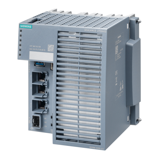
Description of the device The SCALANCE LPE (Local Processing Engine) is an industrial IoT (Internet of Things) device with a Debian GNU/Linux operating system. The device provides computing power for a wide range of Edge applications (Edge Computing). A further main application is the use of Docker containers in industrial environments. -
Page 18: Device View
Description of the device 4.4 Components of the product Device view The following figure shows an overview of the components of the device. 9 10 ① ⑧ CLP slot Levering aid for moving the securing bar with a screwdriver ② ⑨ LED display Securing bar ③... -
Page 19: Spare Parts
Description of the device 4.6 Accessories Unpacking and checking WARNING Do not use any parts that show evidence of damage If you use damaged parts, there is no guarantee that the device will function according to the specification. If you use damaged parts, this can lead to the following problems: •... -
Page 20: Serial Usb Cable
Description of the device 4.6 Accessories 4.6.2 Serial USB cable Component Description Article number Connecting cable Preassembled USB cable with USB Type A and USB 7ML1930-1FN Type B connector, length: 2 m (USB Type A / USB Type B) Pack of 1 4.6.3 SFP transceivers Pluggable transceiver SFP (100 Mbps) Type Property... -
Page 21: Led Display
You can find the corresponding values for the ambient temperature in the section "Technical specifications (Page 61)". LED display The following figure shows the arrangement of the LEDs: SIEMENS SIEMENS USB X1 LED for displaying an alarm LEDs for displaying the port status LEDs for displaying the power supply 4.7.1... -
Page 22: Port Leds
Description of the device 4.7 LED display Meaning during device startup without pressing the "SET" button LED color LED status Meaning during device startup Device startup was completed successfully. Device startup is not complete yet or errors have occurred. Note When using the function extender interface, LED "A" has the following meaning during device startup: •... -
Page 23: L" Led
When using the function extender interface, these LEDs indicate the input via which the SCALANCE switch receives the supply voltage. SET button Position The "SET" button is located on the front of the device. SIEMENS USB X1 USB X1 Figure 4-1 Position of the "SET" button on a SCALANCE LPE9403... -
Page 24: Configuration License Plug (Clp)
Description of the device 4.10 Combo port Configuration License Plug (CLP) SCALANCE LPE has a slot for a CLP (Configuration License Plug) on the top of the enclosure. For more information about suitable memory expansions for SCALANCE LPE, refer to the "Accessories"... -
Page 25: Function Extender Interface
Description of the device 4.11 Function extender interface 4.11 Function extender interface The right side of the enclosure has an interface for connecting the SCALANCE LPE to a compatible SCALANCE switch. This interface is closed with a cover in the delivery state. Connecting the SCALANCE LPE to a SCALANCE switch via this interface results in the following changes: •... - Page 26 Description of the device 4.11 Function extender interface Device Description Article number SCALANCE XCH328 6GK5328-4TS01-2EC2 • 24 x 10 / 100 / 1000 Mbps RJ45 ports • 4 x SFP / SFP+ plug-in transceiver slots with 1 / 10 Gbps • 2 x 2-pin terminal block 24 V DC, power supply connection •...
-
Page 27: Installation And Removal
Installation and removal Safety during installation and removal Safety notices When installing the device, keep to the safety notices listed below. NOTICE Improper mounting Improper mounting may damage the device or impair its operation. • Before mounting the device, always ensure that there is no visible damage to the device. •... - Page 28 Installation and removal 5.1 Safety during installation and removal Safety notices on use in hazardous areas General safety notices relating to protection against explosion WARNING EXPLOSION HAZARD Replacing components may impair suitability for Class 1, Division 2 or Zone 2. WARNING The device is intended for indoor use only.
- Page 29 Installation and removal 5.1 Safety during installation and removal Gc, see section "Certifications and approvals (Page 71)". This is indicated on the type plate. The FO bus connections may run through or in a Zone 1 and Zone 2 hazardous area with these devices. Safety notices when using according to FM If you use the device under FM conditions you must also keep to the following safety notices in addition to the general safety notices for protection against explosion:...
-
Page 30: Mounting Types
Installation and removal 5.2 Mounting types WARNING Open equipment The devices are "open equipment" according to the standard IEC 61010-2-201 or UL 61010-2-201 / CSA C22.2 No. 61010-2-201. To fulfill requirements for safe operation with regard to mechanical stability, flame retardation, stability, and protection against contact, the following alternative types of installation are specified: •... -
Page 31: Mounting On Din Rails
Installation and removal 5.3 Mounting on DIN rails Installation position The following installation position is recommended in standalone operation: Horizontal Horizontal installation of the rack (DIN rail) A reduced maximum temperature may apply in the event of a different installation position in standalone operation; see section "Technical specifications of SCALANCE LPE9403 (Page 61)". -
Page 32: Installation On A Standard S7-300 Rail
Installation and removal 5.4 Installation on a standard S7-300 rail Securing bar in the wall mounting position (as supplied) To install the device on a 35 mm DIN rail complying with DIN EN 60715, follow these steps: 1. Loosen the knurled screw with your hand or a screwdriver. 2. - Page 33 Installation and removal 5.4 Installation on a standard S7-300 rail Figure 5-2 S7-300 mounting rail installation with the securing bar in the wall mounting position Securing bar in the wall mounting position (as supplied) To install the device on an S7-300 mounting rail, follow these steps: 1.
-
Page 34: Installation On A Standard S7-1500 Rail
Installation and removal 5.5 Installation on a standard S7-1500 rail Installation on a standard S7-1500 rail Installation on an S7-1500 mounting rail Note Note the position of the securing bar. When supplied, the securing bar is in the wall mounting position. To change the position of the securing bar, refer to the section "Changing the position of the securing bar (Page 36)". -
Page 35: Wall Mounting
Installation and removal 5.6 Wall mounting Wall mounting Tools To mount the device on a wall, you require the following: • 2 wall plugs with a diameter of 6 mm and a minimum length of 35 mm. • 2 oval-head screws with a diameter of 3.5 mm to 4 mm and a minimum length of 50 mm. Note Depending on the mounting surface, use suitable fittings. -
Page 36: Changing The Position Of The Securing Bar
Installation and removal 5.7 Changing the position of the securing bar Changing the position of the securing bar Rail mounting position - wall mounting position To change the securing bar from the rail mounting position to the wall mounting position follow the steps below: 1. -
Page 37: Connecting A Scalance Switch With A Scalance Lpe9403
Installation and removal 5.8 Connecting a SCALANCE switch with a SCALANCE LPE9403 Connecting a SCALANCE switch with a SCALANCE LPE9403 Position The following figure shows the elements required to connect a SCALANCE switch (Page 25) with a SCALANCE LPE. ① Lock (on the device rear of the SCALANCE switch) ②... - Page 38 Installation and removal 5.8 Connecting a SCALANCE switch with a SCALANCE LPE9403 Installation position If a SCALANCE switch is connected to a SCALANCE LPE, only the following installation position is permitted: Horizontal Horizontal installation of the rack (e.g. DIN rail) Any other installation position can lead to impermissibly high temperatures and damage the devices.
- Page 39 Installation and removal 5.8 Connecting a SCALANCE switch with a SCALANCE LPE9403 5. Press the devices together until they are flush. ① The centering pins click audibly into place. The locking device is automatically pressed up briefly as this happens. 6. Connect the SCALANCE switch to the power supply. The SCALANCE switch supplies the SCALANCE LPE with power over the function extender interface.
-
Page 40: General Notes For Sfp Transceivers
WARNING Use only approved SFP transceivers If you use SFP transceivers that have not been approved by Siemens AG, there is no guarantee that the device will function according to its specifications. If you use unapproved SFP transceivers, this can lead to the following problems: •... -
Page 41: Connecting Up
Connecting up Safety when connecting up Safety notices for operation with a power supply according to NEC Class 2 Operate the device with a power supply according to NEC Class 2. When connecting up the device, keep to the safety notices listed below. WARNING Power supply The device is designed for operation with a directly connectable safety extra low voltage (SELV) - Page 42 Connecting up 6.1 Safety when connecting up Note Safety extra-low voltage The supply of the devices by PELV (Protective Extra Low Voltage) according to DIN VDE 0100-410 or IEC 60364-4-41 is permitted when the generated nominal voltage does not exceed the voltage limits 25 VAC or 60 VDC.
- Page 43 Connecting up 6.1 Safety when connecting up NOTICE Suitable fuse for the power supply cables (corresponds to "Limited Energy") The current on the terminal may not exceed 3 A. Use a fuse for the power supply that is suitable for protection of AC/DC power supply circuits * and protects against currents >...
- Page 44 Connecting up 6.1 Safety when connecting up Safety notices on use in hazardous areas General safety notices relating to protection against explosion WARNING Unsuitable cables or connectors Risk of explosion in hazardous areas • Only use connectors that meet the requirements of the relevant type of protection. •...
- Page 45 Connecting up 6.1 Safety when connecting up WARNING EXPLOSION HAZARD Do not connect or disconnect cables to or from the device when a flammable or combustible atmosphere is present. Safety notices when using the device according to Hazardous Locations (HazLoc) If you use the device under HazLoc conditions you must also keep to the following safety notices in addition to the general safety notices for protection against explosion: WARNING EXPLOSION HAZARD...
-
Page 46: Wiring Rules
Connecting up 6.2 Wiring rules Safety notices when using the device according to ATEX/IECEx and FM If you use the device under ATEX/IECEx or FM conditions, you must also observe the following safety notices in addition to the general safety notices for protection against explosion: WARNING Explosion hazard... -
Page 47: Dc Power Supply
Connecting up 6.3 24 V DC power supply Wiring rules for ... Screw/spring-loaded ter‐ minals Stripped length of the cable 8 - 10 mm Wire end ferrule according to DIN 46228 with plastic ferrule** 8 - 10 mm * AWG: American Wire Gauge ** See note "Wire end ferrules"... - Page 48 Connecting up 6.3 24 V DC power supply Combination of a SCALANCE LPE with a SCALANCE switch via the function extender interface NOTICE Operating risk - Danger of malfunction during device startup If you have connected a SCALANCE LPE to a SCALANCE switch via the function extender interface, the power for the SCALANCE LPE is supplied exclusively via the SCALANCE switch.
-
Page 49: Functional Ground
Connecting up 6.4 Functional ground Position and assignment SIEMENS USB X1 Figure 6-1 Position of the power supply and assignment of the terminal block Contact Assignment 24 V DC Ground Ground 24 V DC Functional ground EMC disturbances are diverted to ground via the functional ground. This ensures the immunity of the data transmission. - Page 50 Connecting up 6.4 Functional ground SIEMENS USB X1 Follow these steps to connect the functional ground: 1. Loosen the grounding screw. 2. Join the grounding terminal and grounding screw together. 3. Tighten the grounding screw with a maximum torque of 0.75 Nm.
-
Page 51: Industrial Ethernet
Unlocking the plug with a screwdriver If installation space is limited, you can unlock the connectors using a screwdriver, see also "SIMATIC NET: IE FC RJ45 Plug 4x2 CAT 6A (https://support.industry.siemens.com/cs/ww/en/ view/102047916)". R-45 connector technology The attachment to Industrial Ethernet uses RJ-45 connected technology with MDI-X assignment. -
Page 52: Optical
Connecting up 6.5 Industrial Ethernet Autonegotiation Autonegotiation means the automatic detection/negotiation of the transmission rate and the operating mode of ports at the opposite end. This makes it possible to configure different devices automatically. Two components connected to a link segment can exchange information about the transfer and can adapt their settings to each other. -
Page 53: Usb Console Interface
Position of the USB console interface (USB socket Type B) Driver for the USB console interface To use the USB console interface under Windows, you must download and install the following driver: Driver (https://support.industry.siemens.com/cs/ww/en/view/109798927) SCALANCE LPE9403 Operating Instructions, 10/2023, C79000-G8976-C599-05... -
Page 54: Usb Interface
Functional disruptions due to cables that are too long The length of the USB cable must not exceed 3 meters to ensure proper function of the USB interface. Longer cables can result in functional disruptions and error messages. Position SIEMENS USB X1 USB X1 Figure 6-3... -
Page 55: Maintenance And Cleaning
Maintenance and cleaning WARNING Unauthorized repair of devices in explosion-proof design Risk of explosion in hazardous areas • Repair work may only be performed by personnel authorized by Siemens. WARNING Impermissible accessories and spare parts Risk of explosion in hazardous areas •... - Page 56 Maintenance and cleaning SCALANCE LPE9403 Operating Instructions, 10/2023, C79000-G8976-C599-05...
-
Page 57: Troubleshooting
Troubleshooting Loading new firmware using TFTP without Web UI Firmware The firmware is signed and encrypted. This ensures that only firmware created by Siemens can be downloaded to the device. NOTICE Observe information on new firmware version The improper use of a new firmware can lead to a malfunction or to failure of the device. - Page 58 Troubleshooting 8.1 Loading new firmware using TFTP without Web UI Using TFTP, you can supply a device with new firmware even when it cannot be reached via the Web UI or the console. This section explains the procedure based on the example of Microsoft Windows.
-
Page 59: Starting The Rescue System When Using The Function Extender Interface
Troubleshooting 8.3 Resetting the configuration Starting the Rescue system when using the Function Extender Interface The function of the SET button is independent of whether a SCALANCE LPE is used in combination with a SCALANCE switch or in standalone mode. The Rescue system can therefore also be started on a SCALANCE LPE which is connected to a SCALANCE switch via the function extender interface. - Page 60 Troubleshooting 8.3 Resetting the configuration SCALANCE LPE9403 Operating Instructions, 10/2023, C79000-G8976-C599-05...
-
Page 61: Technical Specifications
Technical specifications Technical specifications of SCALANCE LPE9403 Technical specifications Connection to Industrial Ethernet Electrical connectors Quantity Connector RJ45 jack Properties Full duplex; MDI-X assignment Transmission rate 10 / 100 / 1000 Mbps Combo ports Quantity Electrical connec‐ Quantity tors Connector RJ45 jack Properties Full duplex;... - Page 62 Technical specifications 9.1 Technical specifications of SCALANCE LPE9403 Technical specifications Power supply Rated voltage 24 V DC Voltage range (incl. tolerance) 19.2 to 28.8 V DC safety extra-low voltage (SELV/PELV) Design Terminal block, 2 x 2-pin Properties Redundant design, galvanically connected to the housing The connected power supply must meet the re‐ quirements of NEC Class 2.
-
Page 63: Mechanical Stability (In Operation)
Technical specifications 9.3 RF radiation according to NAMUR NE21 Technical specifications Dimensions (W x H x D) 134 x 147 x 127 mm Weight 1600 g Installation options • DIN rail mounting • Installation on an S7-300 mounting rail • Installation on an S7-1500 mounting rail •... -
Page 64: Cable Lengths
Technical specifications 9.4 Cable lengths Cable lengths The following cable lengths apply to the device. Cable Permitted cable length IE TP Torsion Cable 0 ... 45 m with IE FC Outlet RJ45 + 10 m TP Cord + 10 m TP Cord IE TP Torsion Cable 0 ... 55 m with IE FC RJ45 Plug 180 IE FC TP Marine/Trailing/Flexible Cable 0 ... 75 m with IE FC Outlet RJ45 + 10 m TP Cord... -
Page 65: Dimension Drawings
Dimension drawings 10.1 SCALANCE LPE9403 dimension drawings Note Dimensions are specified in mm. Front view 12,5 SIEMENS USB X1 ① Securing bar in the rail mounting position ② Securing bar in the wall mounting position (as supplied) SCALANCE LPE9403 Operating Instructions, 10/2023, C79000-G8976-C599-05... - Page 66 Dimension drawings 10.1 SCALANCE LPE9403 dimension drawings Side view SCALANCE LPE9403 Operating Instructions, 10/2023, C79000-G8976-C599-05...
-
Page 67: Dimension Drawings Scalance Xcm-300
Dimension drawings 10.2 Dimension drawings SCALANCE XCM-300 Drilling template for wall mounting ‡ 10.2 Dimension drawings SCALANCE XCM-300 Note Dimensions are specified in mm. SCALANCE LPE9403 Operating Instructions, 10/2023, C79000-G8976-C599-05... - Page 68 Dimension drawings 10.2 Dimension drawings SCALANCE XCM-300 Front view ① Securing bar in the rail mounting position ② Securing bar in the wall mounting position (as supplied). SCALANCE LPE9403 Operating Instructions, 10/2023, C79000-G8976-C599-05...
- Page 69 Dimension drawings 10.2 Dimension drawings SCALANCE XCM-300 Side view ① Securing bar in the rail mounting position ② Securing bar in the wall mounting position (as supplied). SCALANCE LPE9403 Operating Instructions, 10/2023, C79000-G8976-C599-05...
- Page 70 Dimension drawings 10.2 Dimension drawings SCALANCE XCM-300 Drilling template for wall mounting SCALANCE LPE9403 Operating Instructions, 10/2023, C79000-G8976-C599-05...
-
Page 71: Certifications And Approvals
Current approvals on the Internet You will find the current approvals for the product on the Internet pages of Siemens Industry Online Support (https://support.industry.siemens.com/cs/ww/en/ps/26683/cert). Notes for the manufacturers of machines This product is not a machine in the sense of the EC Machinery Directive or the Supply of Machinery (Safety) Regulations (UK). - Page 72 Process Automation DE-76181 Karlsruhe Germany Importer UK: Siemens plc, Manchester M20 2UR You can find the current UK Declaration of Conformity for these products on the Internet pages under Siemens Industry Online Support (https:// support.industry.siemens.com/cs/ww/en/ps/15273/cert). SCALANCE LPE9403 Operating Instructions, 10/2023, C79000-G8976-C599-05...
- Page 73 "SIMATIC NET Product Information Use of subassemblies/modules in a Zone 2 Hazardous Area". You will find this document • on the data medium that ships with some devices. • on the Internet pages under Siemens Industry Online Support (https:// support.industry.siemens.com/cs/ww/en/view/78381013).
- Page 74 Certifications and approvals Note for devices with CLASS 1 LASER Important note on products certified according to Type Examination Certificate KEMA 07ATEX0145 X as of Issue 95 / DEKRA 18ATEX0025 X and IECEx Certificate of Conformity DEK 14.0025X as of Issue 43 / DEK 18.0017X and containing Class 1 optical radiation sources. Note CLASS 1 LASER The device contains optical radiation sources which comply with the limits of Class 1 according...
- Page 75 Certifications and approvals cULus approval for industrial control equipment cULus Listed IND. CONT. EQ. Underwriters Laboratories Inc. complying with • UL 61010-2-201 • CAN/CSA-IEC 61010-2-201 Report no. E85972 cULus Approval for Information Technology Equipment cULus Listed I. T. E. Underwriters Laboratories Inc. complying with •...
- Page 76 • "Industrial Ethernet / PROFINET Industrial Ethernet" System Manual (https:// support.industry.siemens.com/cs/ww/en/view/27069465) • "Industrial Ethernet / PROFINET - Passive Network Components" System Manual (https:// support.industry.siemens.com/cs/ww/en/view/84922825) • "EMC Installation Guidelines" configuration manual (https:// support.industry.siemens.com/cs/ww/en/view/60612658)
- Page 77 Certifications and approvals WARNING Personal injury and property damage can occur The installation of expansions that are not approved for SIMATIC NET products or their target systems may violate the requirements and regulations for safety and electromagnetic compatibility. Only use expansions that are approved for the system. Note The test was performed with a device and a connected communications partner that also meets the requirements of the standards listed above.
- Page 78 Certifications and approvals SCALANCE LPE9403 Operating Instructions, 10/2023, C79000-G8976-C599-05...
-
Page 79: Index
Index " "SET" button, 18, 23, 58, 59 Housing, 62 Ambient conditions, 62 Installation, 62 Approvals, 71 DIN rail mounting, 32 Article numbers, 17, 26 Installation on a mounting rail, 33, 34 Autonegotiation, 52 Wall mounting, 35 Installation on a mounting rail, 33, 34 Cable length, 64 CE mark, 71 Knurled screw, 18, 32, 33, 34 Centering pin, 37 Combo port, 24 Connecting cable, 53... - Page 80 Index S7-300, 33 Safety notices for installation, 27 general, 9 Use in hazardous areas, 9, 27, 41, 42 when connecting up, 41, 42 Scope of delivery, 18 Secure Boot, 16 Securing bar, 18, 32, 33, 34, 68 Serial cable, 20 Serial interface, 53 SFP transceiver, 20, 21 Signaling contact, 21 Spare parts, 19 Spring-loaded terminal, 18, 48 Startup phase, 21 System manual, 76...
Need help?
Do you have a question about the SIMATIC NET SCALANCE LPE9403 and is the answer not in the manual?
Questions and answers