Table of Contents
Advertisement
Quick Links
RA6M3 Group
Renesas RA Family
RA6M Series
Kits: EK-RA6M3 v1
All information contained in these materials, including products and product specifications, represents
information on the product at the time of publication and is subject to change by Renesas Electronics
Corp. without notice. Please review the latest information published by Renesas Electronics Corp.
through various means, including the Renesas Electronics Corp. website (http://www.renesas.com).
www.renesas.com
AI Kit for RA6M3 Microcontroller Group
AIK-RA6M3 v1
User's Manual
Rev. 0.1 October 2023
Advertisement
Table of Contents

Related Manuals for Renesas RA6M Series


Summary of Contents for Renesas RA6M Series
- Page 1 All information contained in these materials, including products and product specifications, represents information on the product at the time of publication and is subject to change by Renesas Electronics Corp. without notice. Please review the latest information published by Renesas Electronics Corp.
- Page 2 Renesas Electronics disclaims any and all liability for any damages or losses incurred by you or any third parties arising from the use of any Renesas Electronics product that is inconsistent with any Renesas Electronics data sheet, user’s manual or other Renesas Electronics document.
- Page 3 Renesas or its affiliates shall in no event be liable for any loss of profit, loss of data, loss of contract, loss of business, damage to reputation or goodwill, any economic loss, any reprogramming or recall costs (whether the foregoing losses are direct or indirect) nor shall Renesas or its affiliates be liable for any other direct or indirect special, incidental or consequential damages arising out of or in relation to the use of this AIK-RA6M3, even if Renesas or its affiliates have been advised of the possibility of such damages.
-
Page 4: Table Of Contents
User’s Manual Renesas RA Family AIK-RA6M3 v1 Contents Kit Overview ..........................3 Assumptions and Advisory Notes ......................5 Kit Contents ..........................6 Ordering Information ........................ 6 Getting Started with Embedded Software Development Using the AIK-RA6M3 ....... 6 Installing the Flexible Software Package and Development Tools ............6 4.1.1... - Page 5 Renesas RA Family AIK-RA6M3, v1 User's Manual Safety Standards ........................... 23 Design and Manufacturing Information .................. 23 Website and Support ......................24 Revision History ..........................25 Figures Figure 1. AIK-RA6M3 Top Side ......................... 4 Figure 2. AIK-RA6M3 Bottom Side ........................4 Figure 3.
-
Page 6: Kit Overview
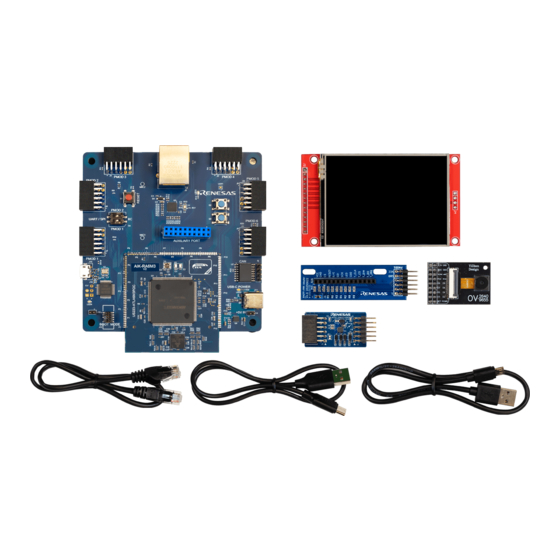
1. Kit Overview The AIK-RA6M3 enables developers to get started with initial firmware development. For more information on the AIK-RA6M3, see www.renesas.com/AIK-RA6M3. The kit includes breakout pin headers for direct access to the RA6M3 microcontroller I/O pins. On-board support is included for several of the most commonly used peripherals, as well as interfaces for several common ecosystem standards. -
Page 7: Figure 1. Aik-Ra6M3 Top Side
Renesas RA Family AIK-RA6M3, v1 User's Manual Figure 1. AIK-RA6M3 Top Side Figure 2. AIK-RA6M3 Bottom Side R12UZ0143EE0100 Rev.0.1 Page 4 of 25 Oct.15.23... -
Page 8: Assumptions And Advisory Notes
Renesas RA Family AIK-RA6M3, v1 User's Manual 1.1 Assumptions and Advisory Notes 1. Tool readiness: This document assumes that the Flexible Software Package, J-Link drivers and development tools are installed on the Windows® PC. 2. Tool experience: You have prior experience working with embedded development environments such as the e2 studio Integrated Solutions Development Environment (ISDE). -
Page 9: Kit Contents
4.1.1 Useful Tips Renesas recommends new users use the “Quick Install” option provided in the installation wizard, to minimize the amount of manual configuration needed. You can always come back and install additional options later. -
Page 10: Quick Setup Guide For Ra Mcus
RA boards are listed at https://github.com/renesas/aiot-ready. The RA boards are pre-programmed with a quick start example project (Asset Movement Detection) that runs when the board is powered on with Renesas ICM-42670-P PMOD Board in PMOD1 and SW1.1 switched to IIC. -
Page 11: Hardware Details
Renesas RA Family AIK-RA6M3, v1 User's Manual 5. Hardware Details 5.1 Kit Architecture AIK-RA6M3 have two functional areas: MCU section (Daughterboard) Peripherals section (Motherboard) The MCU section includes the MCU, Clocks, SDRAM. The Peripherals section includes Power Delivery, User LEDs and Pushbutton Switches, Debug Interface, USB Full Speed, PMOD, Ethernet, CAN and Camera Module peripheral groups. -
Page 12: System Block Diagram
Renesas RA Family AIK-RA6M3, v1 User's Manual 5.1.1 System Block Diagram Figure 5. AIK-RA6M3 Block Diagram 5.2 General Features 5.2.1 Jumper Settings 5.2.1.1 Default Board Configuration The following table describes the default settings for each jumper on the AIK-RA6M3. The Circuit Group for each jumper is the designation found in the board schematic. -
Page 13: Figure 6. Power Supply Options
Renesas RA Family AIK-RA6M3, v1 User's Manual Figure 6. Power Supply Options 5.2.2.2 Option 1: Debug USB 5V may be supplied from an external USB host to the USB Debug connector (J10). Power from this source is connected to the Main System 5V Power. Reverse current protection is provided between this connector and the Main System 5V Power. -
Page 14: Mcu Boot Mode
J-Link On-Board, 2) External Debug using the JTAG connector(J12). The J-Link OB USB Micro-B connection jack (J10) connects the Renesas RA4M2 J-Link MCU to an external USB Full Speed Host, allowing re-programming and debugging of the Main MCU firmware. This is the default debug mode for AIK-RA6M3. -
Page 15: Table 3. Jtag/Swd Connector (J12)
A yellow indicator LED4 provides a visual status of the state of the debug interface. When AIK-RA6M3 is powered on, and LED4 is blinking, this indicates that the Renesas RA4M2 debugger is not connected to a programming host. When LED4 is on solid, this indicates that the Renesas RA4M2 is connected to a programming interface. -
Page 16: Usb Full Speed
Renesas RA Family AIK-RA6M3, v1 User's Manual 5.2.5 USB Full Speed The USB C connection jack (J11) connects the Main MCU USB Full Speed interface to an external USB interface, allowing communications for testing and use of the Main MCU firmware. This connection can be configured as either a USB Device or a USB Host interface. -
Page 17: Pmod 2
Renesas RA Family AIK-RA6M3, v1 User's Manual IIC when changing SW4.1 DIP switch to IIC. This interface may additionally be re-configured in firmware as several other PMOD types. This PMOD interface supports +3.3V devices. Please ensure that any PMOD device installed is compatible with a +3.3V supply. -
Page 18: Pmod 3
Renesas RA Family AIK-RA6M3, v1 User's Manual GPIO1 P500 GPIO1 P500 P500 GPIO2 GPIO2 P507 P507 P507 +3.3V +3.3V +3.3V Figure 10. PMOD 2 5.2.8 PMOD 3 A 12-pin PMOD Type-2A connector is provided at PMOD 3. The Main MCU acts as the SPI master, and the connected module acts as an SPI slave device. -
Page 19: Pmod 6
Renesas RA Family AIK-RA6M3, v1 User's Manual This PMOD interface supports +3.3V devices. Please ensure that any PMOD device installed is compatible with a +3.3V supply. Table 8. PMOD 4 Connector (J2) PMOD 2 Connector AIK-RA6M3 Description Signal/Bus SS/CTS_RTS P504 (SS5/CTS5) -
Page 20: Figure 13. Pmod 5
Renesas RA Family AIK-RA6M3, v1 User's Manual Figure 13. PMOD 5 5.2.11 PMOD 6 A 12-pin PMOD Type-2A connector is provided at PMOD 6. The Main MCU acts as the SPI master, and the connected module acts as an SPI slave device. This interface may additionally be re-configured in firmware as several other PMOD types. -
Page 21: Leds
Renesas RA Family AIK-RA6M3, v1 User's Manual 5.2.12 LEDs There are 5 LEDs provided on the AIK-RA6M3. In addition, the Ethernet connector has built-in link status and link speed LEDs. The behavior of the LEDs on the AIK-RA6M3 is described in the following table. -
Page 22: Figure 17. Reset And User Switches
Renesas RA Family AIK-RA6M3, v1 User's Manual The DIP Switch S4 can be used to change between UART/SPI and ICC for PMOD 1 and PMOD2 Figure 17. Reset and User Switches R12UZ0143EE0100 Rev.0.1 Page 19 of 25 Oct.15.23... -
Page 23: Special Features Access
Renesas RA Family AIK-RA6M3, v1 User's Manual 5.3 Special Features Access 5.3.1 Ethernet The Ethernet interface uses an RMII Ethernet Physical Layer Transceiver (PHY) (U1), connected to an RJ45 standard Ethernet connector (J3) with integrated magnetics and status indicators. The Ethernet clock is sourced from a precision 25 MHz clock crystal connected directly to the Ethernet PHY. -
Page 24: Can/Can-Fd
Renesas RA Family AIK-RA6M3, v1 User's Manual Figure 19. MEMS MICs 5.3.3 CAN/CAN-FD At J9 we have the Controller Area Network bus interface (CAN). Table 16. CAN Port Assignments Description Signal/Bus +3.3V P511 P512 P310 Figure 20. CAN Connector 5.3.4 Camera Module Socket Near the center of the board A 20-pin connector is provided at J6 for the Camera Module Socket connector interface. -
Page 25: Figure 21. Camera Module
Renesas RA Family AIK-RA6M3, v1 User's Manual P414 P413 P412 P411 P410 P015 PWDN P014 P015 PWDN P014 Figure 21. Camera Module R12UZ0143EE0100 Rev.0.1 Page 22 of 25 Oct.15.23... -
Page 26: Certifications
UL 94V-0 7. Design and Manufacturing Information The design and manufacturing information for the EK-RA6M3 v1 kit is available in the “EK-RA6M3v1 Design Package” available on renesas.com/aik-ra6m3. • Design package file name: aik-ra6m3-v1-designpackage.zip • Design package contents Table 18. AIK-RA6M3 Design Package Contents... -
Page 27: Website And Support
Renesas RA Family AIK-RA6M3, v1 User's Manual File (PDF) Schematics aik-ra6m3-v1-schematics File (PDF) Mechanical Drawing aik-ra6m3-v1-mechdwg File (PDF) 3D Drawing aik-ra6m3-v1-3d File (PDF) aik-ra6m3-v1-bom Folder Manufacturing Files Manufacturing Files Folder Design Files Design Files-Altium 8. Website and Support Visit the following URLs to learn about the kit and the RA family of microcontrollers, download tools and documentation, and get support. -
Page 28: Revision History
Renesas RA Family AIK-RA6M3, v1 User's Manual Revision History Description Rev. Date Page Summary 1.00 Oct.15.23 First release document R12UZ0143EE0100 Rev.0.1 Page 25 of 25 Oct.15.23... - Page 29 AIK-RA6M3 User’s Manual Publication Date: Oct.15.23 Published by: Renesas Electronics Corporation...
- Page 30 AIK-RA6M3 v1 – User’s Manual R12UZ0143EE0100...
Need help?
Do you have a question about the RA6M Series and is the answer not in the manual?
Questions and answers