Table of Contents
Advertisement
Quick Links
MENARDS ITEM #641-5054
MODEL #2763FM-23-273
ATTACH YOUR RECEIPT HERE
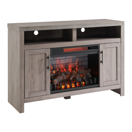
54" ELECTRIC FIREPLACE
ENTERTAINMENT CENTER
ASSEMBLY, CARE & USE INSTRUCTIONS
Serial Number__________________ Purchase Date__________________
Questions, problems, missing parts? Before returning to your retailer, call our customer service department
at 1-855-571-1044 9 a.m. - 5 p.m., EST, Monday - Friday. www.greentouchhome.com.
1
Advertisement
Table of Contents

Related Manuals for Greentouch 2763FM-23-273


Summary of Contents for Greentouch 2763FM-23-273
- Page 1 MENARDS ITEM #641-5054 MODEL #2763FM-23-273 ATTACH YOUR RECEIPT HERE 54" ELECTRIC FIREPLACE ENTERTAINMENT CENTER ASSEMBLY, CARE & USE INSTRUCTIONS Serial Number__________________ Purchase Date__________________ Questions, problems, missing parts? Before returning to your retailer, call our customer service department at 1-855-571-1044 9 a.m. - 5 p.m., EST, Monday - Friday. www.greentouchhome.com.
-
Page 2: Table Of Contents
TABLE OF CONTENTS Package Contents ................................3 Hardware Contents .................................4 Safety Information ................................4 Preparation ..................................8 Assembly Instructions ..............................8 Maximum Recommended Weight Loads........................21 Operating Instructions ..............................22 Care And Maintenance ..............................24 Troubleshooting ................................25 One-Year Limited Warranty ............................26 Replacement Parts List ..............................27... -
Page 3: Package Contents
PACKAGE CONTENTS PART DESCRIPTION QUANTITY PART DESCRIPTION QUANTITY Fireplace Grate Remote Control (Battery Center Shelf (with heater) Inside) Partition Fireplace Brick Wall Left Middle Wall Fireplace Glass Front Right Middle Wall Base Panel Left Outer Wall Base Panel Rail Right Outer Wall Center Support Leg Left Door Right Door... -
Page 4: Hardware Contents
HARDWARE CONTENTS (NOT SHOWN ACTUAL SIZE) Connecting Locknut Wooden Dowel Shelf Pin Door Pull Back panel Long Bolt mounting x 27 x 34 hardware (with x 27 screw) x 18 Bolt Tip Restraint Touch-up Pen Hardware SAFETY INFORMATION Please read and understand this entire manual before attempting to assemble, operate or install the product. This equipment has been tested and found to comply with the limits for Class B digital devices, pursuant to Part 15 of the FCC rules. - Page 5 SAFETY INFORMATION (CONTINUED) Modifications not approved by the party responsible for compliance could void user’s authority to operate the equipment. This Class B digital apparatus complies with Canadian ICES-003. IMPORTANT INSTRUCTIONS When using electrical appliances, basic precautions should always be followed to reduce the risk of fire, electric shock and injury to persons, including the following: DANGER •...
- Page 6 SAFETY INFORMATION (CONTINUED) • Each surface intended to support a load shall have a corresponding statement in the use instructions specifying the maximum intended load for that surface in pounds (kilograms). • Risk of electric shock-connect this furnishing to a properly grounded outlet only. See Grounding Instructions. •...
- Page 7 SAFETY INFORMATION (CONTINUED) Electrical Connection • A 15-Amp, 120-volt, 60 Hz circuit with a properly grounded outlet is required. Preferably, the fireplace will be on a dedicated circuit as other appliances on the same circuit may cause the circuit breaker to trip or the fuse to blow when the heater is in operation.
-
Page 8: Preparation
PREPARATION Before beginning assembly of product, make sure all parts are present. Compare parts with package contents list and hardware contents list. If any part is missing or damaged, do not attempt to assemble the product. Estimated Assembly Time: 50 minutes Tools Required for Assembly (not included): Phillips screwdriver ASSEMBLY INSTRUCTIONS 1. - Page 9 ASSEMBLY INSTRUCTIONS (CONTINUED) 2. As shown in the diagram, insert four wooden dowels (CC) into the corresponding holes on the back of the center shelf (B), align and attach the middle walls (D, E) to the center shelf (B), secure by tightening the four locknuts (BB) with a Phillips screwdriver.
- Page 10 ASSEMBLY INSTRUCTIONS (CONTINUED) 4. Screw three connecting rods (AA) into the holes on the back of the base panel (S). Connecting Rod 5. Insert two wooden dowels (CC) into the corresponding holes on the back of the base panel (S). Align the base panel rail (T) with the inserted wooden dowels and lower into place.
- Page 11 ASSEMBLY INSTRUCTIONS (CONTINUED) 6. Screw four connecting rods (AA) into the holes on the top of the base panel (S). Connecting Rod 7. As shown in the diagram, insert four wooden dowels (CC) into the holes of the base panel (S), align and attach the assembly from step 3 to the base panel (S), secure by tightening the four locknuts (BB) with a Phillips screwdriver.
- Page 12 ASSEMBLY INSTRUCTIONS (CONTINUED) 8. As shown in the diagram, insert the back panels (L) along the grooves of the center shelf (B) and base panel (S). 9. Screw ten connecting rods (AA) into the designated holes on the back of the outer walls (F, G). x 10 Connecting Rod...
- Page 13 ASSEMBLY INSTRUCTIONS (CONTINUED) 10. Insert eight wooden dowels (CC) into the holes on the back of the left outer wall (F), align and attach the left outer wall (F) to the assembly from step 8, secure by tightening the five locknuts (BB) with a Phillips screwdriver. Repeat for the right outer wall (G).
- Page 14 ASSEMBLY INSTRUCTIONS (CONTINUED) 12. Screw the connecting rod (AA) into the designated hole on the top of the center shelf (B). Connecting Rod 13. Insert two wooden dowels (CC) into the holes of the center shelf (B). Attach the partition (C), secure by tightening the locknut (BB) with a Phillips screwdriver.
- Page 15 ASSEMBLY INSTRUCTIONS (CONTINUED) 14. Slide in the center back panel (K) along the grooves on the outer walls (F, G). 15. Screw five connecting rods (AA) into the holes on the back of the top (A). Connecting Rod...
- Page 16 ASSEMBLY INSTRUCTIONS (CONTINUED) 16. Insert six wooden dowels (CC) and five locknuts (BB) into the corresponding holes of the partition (C) and outer walls (F, G). Attach the top (A), secure by tightening the five locknuts (BB) with a Phillips screwdriver. Locknut Wooden Dowel 17.
- Page 17 ASSEMBLY INSTRUCTIONS (CONTINUED) 18. Insert shelf pins (DD) at desired height, ensuring they are level. Place the shelf (J) on the top of the shelf pins (DD). Repeat for the remaining shelf (J). Shelf Pin 19. Place the door pull (EE) into predrilled hole on the right door (I), securing with two door pull screws. Repeat for the remaining door pull (EE).
- Page 18 ASSEMBLY INSTRUCTIONS (CONTINUED) 20. Insert the top pin of the right door (I) into the hole of the plastic nut under the center shelf (B). Pull the latch to re-tract the pin on the bottom of the right door (I) and position it over the hole of the plastic nut on the base panel (S). Release the latch to secure the bottom pin into the base panel (S).
- Page 19 ASSEMBLY INSTRUCTIONS (CONTINUED) 22. Remove the film from the adhesive on the top of the fireplace grate (N) and place the fire log (M) on the center of the fireplace grate (N). 23. Insert the pins of the fireplace glass front (R) into the holes on the base panel (S). Push the top of the fireplace glass front (R) inward until the hole on each side of the frame is adjacent to the hole on both left middle wall and right middle wall panels.
- Page 20 ASSEMBLY INSTRUCTIONS (CONTINUED) 24. NOTE: Use the pre-assembled levelers on the base of the fireplace to level the unit. Twist the levelers counter-clockwise to increase the height, twist clockwise to decrease the height. 1/2 in. WARNING: You must install the tip restraint hardware to help prevent any accidents or damage to the unit. We strongly recommend attaching the tip restraint hardware to a wall stud and your unit.
-
Page 21: Maximum Recommended Weight Loads
MAXIMUM LOAD 6.8 kg / 15 lb MAXIMUM LOAD 6.8 kg / 15 lb MAXIMUM LOAD 6.8 kg / 15 lb SKU#641-5054/Model#2763FM-23-273 DISTRIBUTION: Greentouch USA Inc ADDRESS: 207 Byers Creek Rd Ste D Mooresville, NC 28117-6988 COUNTRY OF ORIGIN: VIETNAM MANUFACTURE DATE: JUL, 2023... -
Page 22: Operating Instructions
OPERATING INSTRUCTIONS Control Panel Remote Control To use the remote control, first remove the plastic tab by gently pulling it out of remote control. Controls and Display The control panel will display the heater setting when the unit power is turned ON. Whichever control icon you press will display the current setting of the corresponding function. - Page 23 OPERATING INSTRUCTIONS (CONTINUED) Heater Function (Control Panel Only) • Press the HEATER ICON to display the current heater setting. • Press the HEATER ICON again to scroll down through the heater settings. Note: Long-hold the icon to quickly scroll through settings. •...
-
Page 24: Care And Maintenance
CARE AND MAINTENANCE • Make sure the unit is turned OFF, unplugged and the heating elements of heater are cool whenever you are cleaning the heater or fireplace. • Clean the metal trim using a water-dampened soft, clean cloth. DO NOT use brass polish or household cleaners as these products will damage the metal trim. -
Page 25: Troubleshooting
TROUBLESHOOTING PROBLEM POSSIBLE CAUSE CORRECTIVE ACTION Error E1 displayed on The overheat sensor has Unplug unit, wait 15-20 minutes, then the sensor will reset control panel. been engaged. itself. Plug the unit back in and turn on the heater. If the problem persists, call customer service (1-855-571-1044). -
Page 26: One-Year Limited Warranty
ONE-YEAR LIMITED WARRANTY The manufacturer warrants that your new electric fireplace is free from manufacturing and material defects for a period of one year from date of purchase, subject to the following conditions and limitations. Install and operate this electric fireplace in accordance with the installation and operating instructions furnished with the product at all times. -
Page 27: Replacement Parts List
GRATE A Remote Control RC-HE85EL02 Heater-black KDI-01-23-M Fireplace Glass Front PU17-1408FM-FIREPLACE GLASS DOOR Shelf Pin B1044 Door Pull PH-WNA10481S-MB DOOR PULL Tip Restraint Hardware ANTI-TIP HARDWARE SET2 Touch-up Pen M-1108 KD Hardware Pack PH-2763FM-23-273-HARDWARE PACK Door Catch PU-DOOR CATCH-BLACK Leveler T-1007...
Need help?
Do you have a question about the 2763FM-23-273 and is the answer not in the manual?
Questions and answers