
Related Manuals for YitaHome GA2305-1


Summary of Contents for YitaHome GA2305-1
- Page 1 GA2305-1 LHHY-V 1 12X16 FT Item no. Reference Image Qty.
- Page 2 ASSEMBLY INSTRUCTIONS Item no. Reference Image Qty. Item no. Reference Image Qty. Item no. Reference Image Qty. X128...
- Page 3 ASSEMBLY INSTRUCTIONS Item no. Reference Image Qty. Item no. Reference Image Qty. X168 M6X16mm M6X15mm M5X12mm ST4.8X12mm M6X25mm M6X35mm...
- Page 4 ASSEMBLY INSTRUCTIONS 4pcs 4pcs 12pcs...
- Page 5 ASSEMBLY INSTRUCTIONS 2pcs 2pcs 2pcs 2pcs 4pcs 32pcs 128pcs When connecting B and B1 via P,C and C1 via P, make sure that 1 holes on part P (as shown in the picture) should be facing upwards. Do not install it upside down.
- Page 6 ASSEMBLY INSTRUCTIONS 16pcs 16pcs...
- Page 7 ASSEMBLY INSTRUCTIONS 4pcs 4pcs 16pcs...
- Page 8 ASSEMBLY INSTRUCTIONS 4pcs 4pcs 24pcs 4pcs...
- Page 9 ASSEMBLY INSTRUCTIONS...
- Page 10 ASSEMBLY INSTRUCTIONS 16pcs 8pcs 4pcs 4pcs 4pcs...
- Page 11 ASSEMBLY INSTRUCTIONS 4pcs...
- Page 12 ASSEMBLY INSTRUCTIONS 6pcs 24pcs 6pcs 6pcs 6pcs 12pcs...
- Page 13 ASSEMBLY INSTRUCTIONS 18pcs...
- Page 14 ASSEMBLY INSTRUCTIONS 2pcs...
- Page 15 ASSEMBLY INSTRUCTIONS 10pcs 2pcs 2pcs 4pcs...
- Page 16 ASSEMBLY INSTRUCTIONS 4pcs 4pcs 2pcs Before installing Parts R1/R2/R3, remove protective films (with side marks) on both the front and back sides. After removal, there will be no mark and minimal difference between the sides. Therefore, pay close attention to directions before removal.
- Page 17 ASSEMBLY INSTRUCTIONS 10pcs 2pcs 2pcs 4pcs...
- Page 18 ASSEMBLY INSTRUCTIONS 2pcs 4pcs 4pcs 2pcs 4pcs 4pcs Before installing Parts Q/Q1/Q2, remove protective films (with side marks) on both the front and back sides. After removal, there will be no mark and minimal difference between the sides. Therefore, pay close attention to directions before removal.
- Page 19 ASSEMBLY INSTRUCTIONS 2pcs 4pcs 4pcs 4pcs 4pcs 4pcs 4pcs Before installing Parts Q/Q3/Q4, Q5/Q6remove protective films (with side marks) on both the front and back sides. After removal, there will be no mark and minimal difference between the sides. Therefore, pay close attention to directions before removal.
- Page 20 ASSEMBLY INSTRUCTIONS 2pcs 4pcs 4pcs 4pcs 6pcs 10pcs...
- Page 21 ASSEMBLY INSTRUCTIONS 4pcs Pay attention to the sidewall curtain's installation position.
- Page 22 ASSEMBLY INSTRUCTIONS 4pcs Note: Attach 1 to 2 to secure parts S (netting) and T (curtains) together. Attach 1 to 3 to secure the back curtain (T). Attach 1 to 3 to secure the front netting (S). Pay attention to the sidewall Hang the hook attached to netting's installation position.
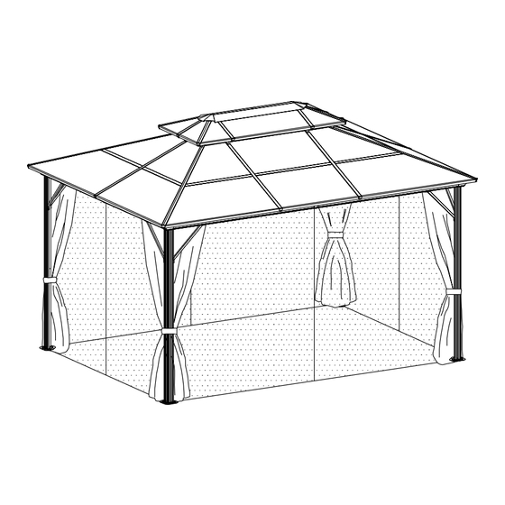
- Page 23 ASSEMBLY INSTRUCTIONS 12pcs Installation Completed Cement surfaces To improve wind resistance, Expansion screws are essential for be sure to complete this installation stability on cement surfaces, step. If expansion screws or ground All are included in the accessories nails are not installed,strong winds package.
Need help?
Do you have a question about the GA2305-1 and is the answer not in the manual?
Questions and answers
Hi I’m on page 15 step 12. I’m confused on how G5 and G6 should be placed properly ?
At step 12 on page 15 of the YitaHome GA2305-1 manual, parts G5 and G6 should be placed in the following order: G5, G6, Ea, Ea, E1, E1. This suggests that G5 and G6 are installed first, followed by two Ea parts and two E1 parts. Ensure correct orientation and alignment during assembly.
This answer is automatically generated
Crappy instructions and customer service. I am returning merchandise for a full credit. unacceptable response from amateur's.
Parts B2 and B3 are missing. Need ASAP to finish project.
Parts B2 and B3 are missing