Advertisement
Quick Links
KMT - Kraus Messtechnik GmbH
Gewerbering 9, D-83624 Otterfing, Germany, 08024-48737, Fax. 08024-5532
Home Page http://www.kmt-telemetry.com, Email: info@kmt-telemetry.com
H
a
H
a
INSTRUCTIONS FOR QUALIFIED PERSONNEL ONLY!
T
T
l
f
-
r
i
n
g
h
l
f
-
r
i
n
g
h
O
p
e
r
a
t
i
n
O
p
e
r
a
t
i
n
Picture show two set's as example
1
-
P
C
M
1
-
P
C
M
o
u
s
i
n
g
o
u
s
i
n
g
g
I
n
s
t
r
u
g
I
n
s
t
r
u
o
n
s
h
a
f
t
o
n
s
h
a
f
t
c
t
i
o
n
s
c
t
i
o
n
s
Advertisement

Related Manuals for KMT T1-PCM


Summary of Contents for KMT T1-PCM
- Page 1 KMT - Kraus Messtechnik GmbH Gewerbering 9, D-83624 Otterfing, Germany, 08024-48737, Fax. 08024-5532 Home Page http://www.kmt-telemetry.com, Email: info@kmt-telemetry.com Picture show two set’s as example INSTRUCTIONS FOR QUALIFIED PERSONNEL ONLY!
- Page 2 Attention • Please note the general danger notes at rotating machines before use! • Use only shielded sensor cable • When used on rotating shafts, all connections must be soldered. Safety notes for inductive powering • The device should only applied by instructed personnel. •...
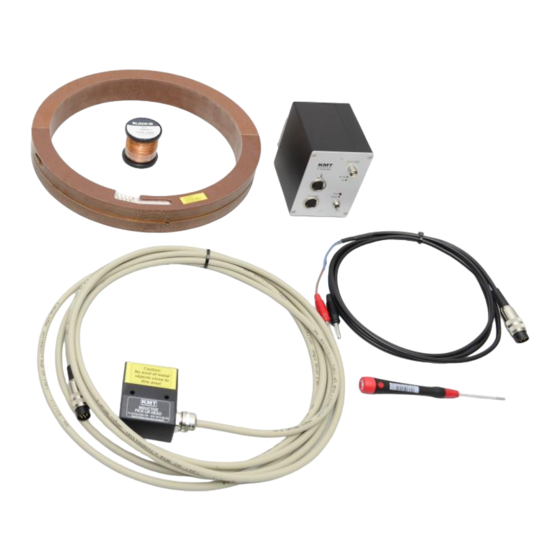
- Page 3 T1-PCM-SET- RING: CUL wire T1-PCM-DEC - (Decoder) 0.5mm for coil with +/-10V out (Enamelled copper wire) RING with embedded T1-STG electronic DC-Power cable Inductive Pickup/Powerhead Allen key to with 5m cable activate AZ switch Picture show two set’s as example...
- Page 4 Technical Data Transmitting Part RING - STG: T1-PCM-STG Strain gage: Full and half bridge >=350 Ohm, Excitation: 4 VDC (fixed) Gain: 250-500-1000-2000 standard 500-1000-2000-4000 or 1000-2000-4000-8000 on request! Gain and Sensitivity Gain 250 = +/-10mV/V Gain 2000 = +/-1.250mV/V Gain 500 = +/-5mV/V Gain 4000 = +/-0.625mV/V...
- Page 5 Transmitting RING pin connection STG: See recommend winding at sticker on ring! Use wire CUL 0.50 – 0.63mm Make a wire bridge and final solder it together! Restart the system after gain setting!!! (Power OFF/ON) A new Auto Zero at the decoder is requirement! Gain 250-2000 or optional Gain 500-4000 Technical Data are subject to change without notice! Version 2021-02...
- Page 6 Technical Data Transmitting Part RING – Pt100: T1-PCM-Pt100 Pt100 thermo sensor Measurement range -50 to 250°C or -50 to 500°C (selectable by solder bridge!) Analog signal bandwidth: 0 - 10 Hz (-3 dB) Operating temperature: - 45 to + 85 °C Resolution 16bit Scanning rate 6.41 kHz...
- Page 7 Transmitting RING pin connection Pt100: See recommend winding at sticker on ring! Use wire CUL 0.50 – 0.63mm GND= Shield Make a wire bridge and final solder it together! Restart the system after gain setting!!! (Power OFF/ON Range of -50 to 250°C or -50 to 500°C Technical Data are subject to change without notice! Version 2021-02...
- Page 8 Transmitting RING: 5-10 Windings CUL 0.5-0.63mm (see recommend winding at sticker on ring!) Fix well the coil after installation with epoxy resin around every 20° in diameter or total around Distance 3-20mm Magnetic field Typical: 8-10mm Technical Data are subject to change without notice! Version 2021-02...
-
Page 9: Example Of Installation
Example of installation: Technical Data are subject to change without notice! Version 2021-02... - Page 10 Transmitting RING: On shaft you will get a gab of about 3mm at right mounting! Caution: Mount screws with care! Technical Data are subject to change without notice! Version 2021-02...
- Page 11 Example draw of a transmitting RING for shaft 250mm: Technical Data are subject to change without notice! Version 2021-02...
- Page 12 Function: Receiving inductive PCM modulated data from the coil of the T1-PCM-STG unit Distance between the transmitter coil and the pickup is 5-30*mm Output to T1-PCM-Decoder: Via 6-pol. Tuchel plug incl. 5m cable Operating temperature: - 10 to +80 °C Dimensions: 53x66x30mm (without cable) Weight: 200 grams (without cable!) Housing: splash-water resistant IP65 (except connector).
- Page 13 Yellow ON- successful AZ LED ON = Error data transmission Yellow OFF- not successful AZ LED Flashing = Distance between Coil If flashing, call support of KMT, and Pickup is too error in EPROM far away AZ button Data input from Pickup and Add.
- Page 14 Receiving part - dimensions: Weight: 0.750 kg Technical Data are subject to change without notice! Version 2021-02...
-
Page 15: Pin Connection
Pin connection: Powerhead / Pickup Standard version for distance of 5-25mm (Optional 5-35mm) DC-Power cable Technical Data are subject to change without notice! Version 2021-02... - Page 16 Following must be considered at the mounting of the inductive power head at T1-PCM Shaft with Cu wire Coil Magnetic field 25-30mm Don’t use for mounting any kind metal in this area (25-30mm)! Otherwise flow magnetic energy in the metal also and...
- Page 17 Dimensions Powerhead / Pickup standard cable right side out Technical Data are subject to change without notice! Version 2021-02...
- Page 18 Dimensions Powerhead / Pickup (CRS at standard and XL) draw CRS = cable rear side out! Technical Data are subject to change without notice! Version 2021-02...
- Page 19 Kraus Messtechnik GmbH Gewerbering 9, D-83624 Otterfing, +49-8024-48737, Fax. +49-8024-5532 – Germany Home Page http://www.kmt-gmbh.com Email: info@kmt-gmbh.com Konformitätserklärung Declaration of Conformity Declaration de Conformité KMT - Kraus Messtechnik GmbH Nous Anschrift Gewerbering 9, D-83624 Otterfing, Germany Address Adress erklären in alleiniger Verantwortung, daß das Produkt declare under our sole responsibility, that the product declarons sous notre seule responsibilité, que le produit...
Need help?
Do you have a question about the T1-PCM and is the answer not in the manual?
Questions and answers