Advertisement
Quick Links
KMT - Kraus Messtechnik GmbH
Gewerbering 9, D-83624 Otterfing, Germany, 08024-48737, Fax. 08024-5532
Home Page: http://www.kmt-telemetry.com, Email: info@kmt-telemetry.com
T
E
T
D
i
g
i
t
a
l
H
i
g
D
i
g
i
t
a
l
H
i
g
G
a
g
e
a
n
G
a
g
e
a
n
"Gain and Auto Zero setting direct from Receiver Side!"
Easy to assemble and operate
For strain gages or IPC sensors
Strain gage sensors (>350 Ohm)
Full- and half bridge configuration
Excitation fixed 4 Volt DC
Auto-Zero adjustment - Setting receiver side
Gain: 250-8000 - Setting receiver side
External shunt calibration
INSTRUCTIONS FOR QUALIFIED PERSONNEL ONLY!
L
1
-
P
C
E
L
1
-
P
C
U
s
e
U
s
e
h
D
a
t
a
R
a
t
h
D
a
t
a
R
a
d
I
C
P
A
p
p
d
I
C
P
A
p
p
M
-
H
S
M
-
H
S
r
M
a
n
u
r
M
a
n
e
T
e
l
e
m
e
t
r
t
e
T
e
l
e
m
e
t
l
i
c
a
t
i
o
n
s
o
l
i
c
a
t
i
o
n
s
o
ICP current 4mA, Gain selectable to: 2-4-8-16
Digital transmission realized inductively
Distance up to 50mm
No influence through radio frequency
Many systems can operated at the same time
Signal bandwidth 0...50kHz
Output +/-10V and digital for interface (Option)
System accuracy <0.2%
-
B
A
T
T
-
B
A
T
T
a
l
u
a
l
y
S
y
s
t
e
m
f
r
y
S
y
s
t
e
m
n
R
o
t
a
t
i
n
g
n
R
o
t
a
t
i
n
g
(Scanning rate 104kHz)
o
r
S
t
r
a
i
n
f
o
r
S
t
r
a
i
n
S
h
a
f
t
s
S
h
a
f
t
s
Advertisement

Related Manuals for KMT TEL1-PCM-HS-BATT


Summary of Contents for KMT TEL1-PCM-HS-BATT
- Page 1 KMT - Kraus Messtechnik GmbH Gewerbering 9, D-83624 Otterfing, Germany, 08024-48737, Fax. 08024-5532 Home Page: http://www.kmt-telemetry.com, Email: info@kmt-telemetry.com “Gain and Auto Zero setting direct from Receiver Side!” Easy to assemble and operate ICP current 4mA, Gain selectable to: 2-4-8-16 ...
-
Page 2: General Description
LED bar indicator. When the AZ completes the LED continuously illuminates. A continued flashing of the yellow LED indicates some error in the AZ electronics. In this case please contact the support of KMT. Additional to the AZ you have the possibility to calibrate the bridge by external shunt. - Page 3 Technical Data - rotating part TEL1-PCM-HS-BATT-STG Strain gage: Full and 1/2 bridge >350 Ohm, Excitation: 4 VDC (fixed) Gain: 250; 500; 1000; 2000; 4000; 8000 (selectable from receiver side) Sensitivity STG Module Input vs Decoder Output Gain 250 = 4mV/V Gain 2000 = 0.500mV/V...
- Page 4 Function: Receiving inductive magnetic field in PCM modulated code Distance between the transmitter coil and the pickup is 50mm Output to TEL1-PCM-HS-BATT Decoder via 5pol. Tuchel plug incl. 5m cable. Cable length standard 5m, optional 20m Operating temperature: - 10 to +80 °C...
- Page 5 Transmitting Part: Strain gage connection The pins for battery Coil connection +6-9V and GND Battery Inductive coil Version 2012-10 Technical Data are subject to change without notice!
-
Page 6: Block Diagram
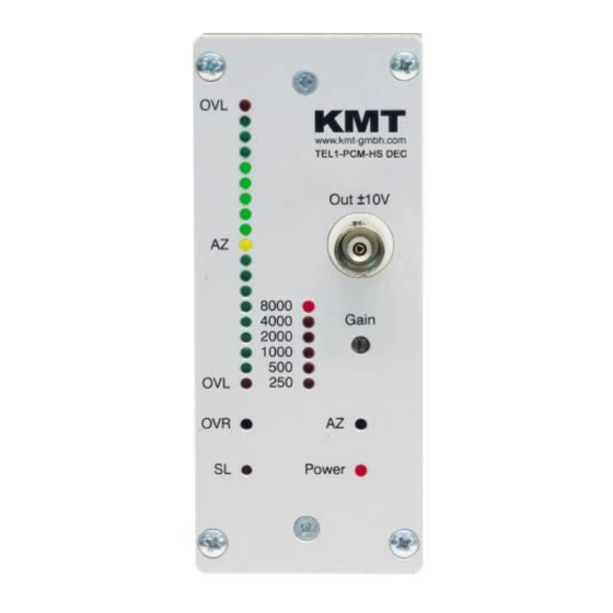
Block diagram: Note: The Powerhead must be fixed in the middle of the coil in a distance from 5 up to 50 mm. Version 2012-10 Technical Data are subject to change without notice! - Page 7 Receiving Part: Front Positive Baragraph LED With overload indicator Auto Zero LED Analog output +/-10V ON = successful OFF = Not successful Gain switch Negative Bargraph LED With overload indicator Reset button of AZ button overload indicator LED ON = Error data transmission Power On LED LED Flashing = Battery voltage lower 6V...
- Page 8 Pin connection cable: Pickup Distance of 5-100mm DC-Power cable Version 2012-10 Technical Data are subject to change without notice!
-
Page 9: Shaft Installation
Shaft Installation Fix with 2 layers of mounting tape around the shaft Mount 2 layers of the special ferrite tape around the shaft. (each layer seperatly, without overlap!) Coil, depends of shaft diameter 4-25 parallel windings of 0.5 CUL wires (see table for help) Fix with 3-4 layers of mounting tape around the shaft Version 2012-10 Technical Data are subject to change without notice! - Page 10 Solder the wires of the coil on the pins of TEL1- PCM-HS-STG “2x Coil” 10 layers of the special mounting tape (width 50mm) around the shaft. We recommend add. use a steel hose clamp for final fixing!! 10.) steel hose clamps Caution: Fix TEL1-PCM-HS-STG-BATT module with at least 10 layers (width 50mm) of the special mounting tape around the shaft.
- Page 11 Find the correct amount of windings The number of windings depends on several factors. The most important influential factors are the diameter, the materiel of the shaft and the environment around the shaft. The table standing below will help you to find the right number windings for steel shafts.
- Page 12 Kraus Messtechnik GmbH Gewerbering 9, D-83624 Otterfing, +49-8024-48737, Fax. +49-8024-5532 – Germany Home Page http://www.kmt-gmbh.com Email: info@kmt-gmbh.com Konformitätserklärung Declaration of Conformity Declaration de Conformité KMT - Kraus Messtechnik GmbH Nous Gewerbering 9, D-83624 Otterfing, Germany Anschrift Address Adress erklären in alleiniger Verantwortung, daß das Produkt declare under our sole responsibility, that the product declarons sous notre seule responsibilité, que le produit...
- Page 13 KMT - Kraus Messtechnik GmbH Gewerbering 9, D-83624 Otterfing, Germany, 08024-48737, Fax. 08024-5532 Home Page http://www.kmt-gmbh.com, Email: info@kmt-gmbh.com Version 2012-10 Technical Data are subject to change without notice!
- Page 14 Inductive power supply set Picture shows standard Inductive Power Supply for diameter up to 300mm Power supply for power head 25 and 50mm mounting tape Ferrite tape CU wire 0.5mm to fix coil on shaft 30mmx3m IND-PWR AC/DC module Input: AC from coil Power Head with cable Output 6.5VDC 100mA DC Power cable...
- Page 15 Installation of coil for inductive powering on shaft Attach for electromagnetic insulation “Ferrite Tape” - 2 x layers Ferrite-Tape around the shaft - Fixed with 2 layers mounting tape Wind the 0.5 mm enameled copper wire around the shaft: - 4-25 windings for 500-20mm diameter Other diameter on request! Note: “The inductive load of the IND-PWR AC/DC module and the capacitor in the Power Head must be in...
- Page 16 Optimum windings for steel shafts 1200 1000 Windings Diameter (mm) Windings Fine adjustment capacitor We recommend a capacitor decade e.g parallel to coil 100-200nF (Type MKT or MKS 250V) 1000 100-200nF (Type MKT or MKS 250V) 100-200nF (Type MKT or MKS 250V) 100pF ..
- Page 17 The pins “AC IN” are the AC power input from the coil. On the pins “+6.5” and “GND“ you get a stabilized output voltage of 6.5V DC. The control LED will lights up, as soon as the power head is switched on and at AC IN Control LED the right position - close enough to the coil on the shaft.
- Page 18 Fixing of IND-PWR AC/DC module and TEL1-PCM-HS-BATT Fix all modules with at least 10 layers of the special mounting tape around the shaft. According to the shafts RPM and diameter it’s particularly paid attention to safe mounting of the components.
- Page 19 Following must be considered at the mounting of the inductive power head Shaft with Cu wire Coil Magnetic field 25-30mm Don’t use for mounting any kind metal in this area (25-30mm)! Otherwise flow magnetic energy in the metal also and degrease the distance between power head and coil (on shaft)! Example of mounting plate,...
- Page 20 Dimensions Powerhead Drill d= 4,3mm Cable length 5m Optional 10...20m 33mm Version 2012-10 Technical Data are subject to change without notice!
- Page 21 Attention Use only shielded sensor cable When used on rotating shafts, all connections must be soldered. Mounting of the modules on a shaft must be first fixed with mounting tape (only for prefixing) and then with a hose clamps!!! Safety Notes for Inductive Powering ...
Need help?
Do you have a question about the TEL1-PCM-HS-BATT and is the answer not in the manual?
Questions and answers