Advertisement
Quick Links
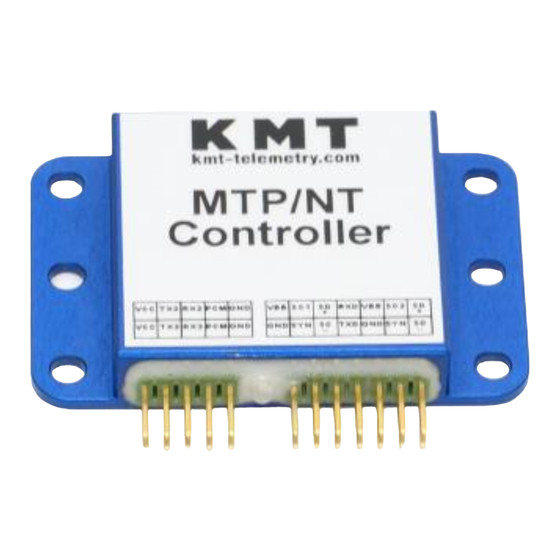
KMT - Kraus Messtechnik GmbH
Gewerbering 9, D-83624 Otterfing, Germany, +49-8024-48737, Fax.-5532
Home Page http://www.kmt-telemetry.com, Email: info@kmt-telemetry.com
Sophisticated multi-channel telemetry system
for rotating application, fully software
programmable with 16 bit resolution
INSTRUCTIONS FOR QUALIFIED PERSONNEL ONLY!
•
2 to 256 channels
•
Signal bandwidth up to 24000 Hz
•
Inputs: STG, IEPE, VOLT, THERMO
•
Auto offset compensation (
•
4V Bridge excitation
•
STG Input ranges ±40 to ±0.3 mV/V
MTP-NT
User Manual
)
STG/VOLT
•
16 bit ADC (internal 18 bit)
•
Fully software programmable
•
Inductive or battery powered
•
Rugged housing, water protected
•
Analog output +/- 10V
•
Digital Ethernet output for PC
Advertisement

Related Manuals for KMT MTP-NT


Summary of Contents for KMT MTP-NT
- Page 1 KMT - Kraus Messtechnik GmbH Gewerbering 9, D-83624 Otterfing, Germany, +49-8024-48737, Fax.-5532 Home Page http://www.kmt-telemetry.com, Email: info@kmt-telemetry.com MTP-NT User Manual Sophisticated multi-channel telemetry system for rotating application, fully software programmable with 16 bit resolution INSTRUCTIONS FOR QUALIFIED PERSONNEL ONLY! •...
-
Page 2: Safety Notes
Safety notes • The device should only applied by instructed personnel. • The power head emits strong magnetic radiation at 30-60 kHz to a distance of 300 mm. Therefore persons with cardiac pacemakers should not work with this device! • Magnetic data storage media should be kept in a distance of at least 3m from the power head to avoid data loss. -
Page 3: Short Description
Each 2-channel sensor module is equipped with signal conditioning, anti-aliasing filters, analog-to-digital converters (16 bit) and a digital communication bus connection. All these up to 128 modules (=256 channels) will be controlled by the MTP-NT-Controller module via a daisy-chain system bus (extendable to several meters). By this concept it’s possible to install the acquisition modules close to the sensor to have short connections for the analog sensor lines. - Page 4 MTP-NT connection overview Version 2018-14-CN Technical Data are subject to change without notice!
- Page 5 MTP-NT housing dimensions for 2- and 4-channels Version 2018-14-CN Technical Data are subject to change without notice!
- Page 6 MTP-NT Bock diagram Version 2018-14-CN Technical Data are subject to change without notice!
- Page 7 MTP-NT Modules mounting plate example for shaft diameters 100-200 or 150-250mm Version 2018-14-CN Technical Data are subject to change without notice!
- Page 8 MTP-NT – Setting of parameters or firmware update of all modules via RS232 All parameters are programmable over RS232, RS232-USB-adapter or *Bluetooth COM M (*require MTP-NT Bluetooth module COM M) Inductive data coil RS232 connection connection BUS I/O BUS I/O...
- Page 9 Download latest firmware, windows config software, user manual and other tools under: https://www.kmt-telemetry.com/support/mtp-nt/ Version 2018-14-CN Technical Data are subject to change without notice!
- Page 10 Firmware: This is the latest firmware for all MTP-NT systems. All MTP-NT modules (no matter what function they have) work with the same firmware. Therefore, with a single operation a complete MTP-NT system can be updated to the latest firmware version. Just double-click nt_update.exe and the update will start.
- Page 11 8 bits • stop bits must select 1 bits • save settings permanently (yes) • After your settings, reset MTP-NT system with power OFF/ON and the setup will start automatically ……. Version 2018-14-CN Technical Data are subject to change without notice!
- Page 12 Download latest firmware, windows config software, user manual and other tools under: https://www.kmt-telemetry.com/support/mtp-nt/ ntconfig.zip Download ntconfig.zip file and extract zip file to e.g. desktop Open ntconfig folder and start ntconfig.exe. This software must not install on windows. You can start direct from...
- Page 13 Load and Save Configuration file function coming soon! Setup your serial bus connection Select COM port of your USB/COM adapter, e.g. COM3 Version 2018-14-CN Technical Data are subject to change without notice!
- Page 14 Now the setup will download from the MTP-NT-CONTOLER in real time: Green frame = This function coming soon! Red frame is full in function! Version 2018-14-CN Technical Data are subject to change without notice!
- Page 15 MTP-NT – Easy to connect with daisy-chain connection with the same MTP-NT-BUS-C cable The bus is extendable to several meters! AMP "Locking-Clip" crimp connectors withstand ultra-harsh vibration and shock environment Caution: Locking-Clip must be complete connected! GOOD �� BAD ☹...
-
Page 16: Front Side View
(10–30V DC) IND-Pickup head connection Plug-side Optional BNC16/32 Box. Connect on 37pol D-Sub MTP-NT –DEC8/16/24/32 System Parameters: Channels 8,16,24 or 32x +/-10 V analog outputs via D-sub female socket Resolution: 16 bit D/A converter, with smoothing filter Power supply input: 10-30 Vdc, power consumption <... - Page 17 MTP-NT-DIG-DEC-V2 Receiver unit with ethernet (LAN) output Inductive transmission 45 MHz version up to 5000 Mbit (10000Mbit on special request!) Field strength indicator LAN OUT Sync LED Error LED Low Batt. LED use! Active level LED of Pickup ON/OFF head...
- Page 18 MTP-NT-DIG-DEC-V2 ethernet data format: Version 2018-14-CN Technical Data are subject to change without notice!
-
Page 19: Data Frame
32 bit Barker Synch Code + 16x16 bit Data + 32 bit reserved (Frame Nr.3 = CH33..Ch48) + 32 bit Barker Synch Code + 16x16 bit Data + 32 bit reserved (Frame Nr.4 = CH49..Ch64) MTP-NT DEC4/8/16/24/32 with analog output via BNC (4/8) or Sub-D 16/24/32 4 CH... - Page 20 MTP-NT STG - Acquisition module for 2 channels strain gages (STG) MTP-NT-STG2 Acquisition module for 2 strain gauges Full, half and quarter bridge (≥ 350 Ω) Full, half and quarter bridge (120 Ω) Fixed excitation 4 Vdc Offset compensation by auto zero Manual offset shifting after auto zero Gain 62.5-8000 (40 to 0.3 mV/V)
- Page 21 Version 2018-14-CN Technical Data are subject to change without notice!
- Page 22 MTP-NT ICP - Acquisition module for 2 channels IEPE sensor MTP-NT-IEPE2/ICP ® Acquisition module for 2 IEPE/ICP sensors Current EXC. 4mA Gain: 1-2-4-8-16-32 Signal bandwidth 3 Hz to 24000Hz* (*see table of cut-off-frequency) ADC Resolution 16 Bit Gain uncertainty < 0.1%...
- Page 23 MTP-NT VOLT - Acquisition module for 2 channels VOLT inputs MTP-NT-VOLT Acquisition module for 2x high level inputs Input ranges ±10 to ±0.08 V Signal bandwidth 0 Hz to 24000 Hz* (*see table of cut-off-frequencies) +4 V sensor excitation max. 20 mA ADC Resolution 16 Bit Measurement uncertainty <...
- Page 24 MTP-NT THERMO - Acquisition module for 2 channels THERMO inputs MTP-NT-THERMO 2 Acquisition module for 2x Temperature Sensor Inputs galvanically isolated (max. potential difference 32 Vdc) Lowpass filter 1 Hz to 32 Hz (programmable) RTD Sensor types: PT100, PT500, PT1000...
- Page 25 Version 2018-14-CN Technical Data are subject to change without notice!
- Page 26 MTP-NT CON-IND-Tx - Controller for 256 channels with integrated IND-Tx MTP-NT-CON-IND-Tx Controller 1- 128 acquisition modules = 256 channels Output: PCM IND-Transmitter included Programmable via RS232/USB adapter and remote software Power supply: VBB= 6 to 9 Vdc Current consumption 150 mA...
- Page 27 MTP-NT IND-PWR - AC/DC Module for inductive power transmission MTP-NT IND-PWR 6V AC/DC Module for inductive power Input: 30-60 kHz 10-40V AC Output: 6.1 Vdc Current: up to 2400 mA (more on request) Weight: 40 grams Vibration: 5 g Shock: 3000 g Don’t power ON without connected Analog...
- Page 28 Instructions for adjusting the resonance The secondary coil for power transmission creates a parallel resonant circuit with a capacitor, which must be tuned to the frequency of the power generator, so that the best possible efficiency is achieved. This (switchable) capacitor is installed in the power module;...
- Page 29 Inductive transmission (2500kbit) with MTP-NT-IND-TX-RX with 45MHz carrier! With 45MHz carrier is only 1x winding necessary! Attach for electromagnetic insulation “Ferrite Tape” 2 x one layer around the shaft. Strip the isolation from the end of the wire with a skinning tool or head up you soldering iron over 450°C to burn off the insulation...
- Page 30 MTP-NT CON-IND-TX with 45MHz carrier! Pickup head (2500kbit) Inductive Pick-Up head mount in this position! Distance between head and Tx coil can be up to 100mm Typical 50mm, distance deepens of application!! CAUTION: If you want to install also an inductive power coil close to the data coil, the minimal distance must be <5mm!
- Page 31 Picture of IND-PICKUP-HEAD 45MHz IND-PICKUP-HEAD 45MHz - cable rear side (radial to shaft) IND-PICKUP-HEAD 45MHz – cable right side (axial to shaft) Version 2018-14-CN Technical Data are subject to change without notice!
- Page 32 Dimensions of IND-PICKUP-HEAD 45MHz - cable rear side (radial to shaft) Version 2018-14-CN Technical Data are subject to change without notice!
- Page 33 Dimensions of IND-PICKUP-HEAD 45MHz – cable right side (axial to shaft) Version 2018-14-CN Technical Data are subject to change without notice!
- Page 34 MTP-NT-DEC 8/16/32 Receiver unit for max 32 Channels output via 37 pol. Sub D (radio transmission version with HF BOX Quad with 4 receiver 1250 … 5000kbit) PCM OUT Pin 1 ----- Pin 2 = PCM + (pink wire) Pin 3 = PCM -- (blue wire) 4x HF Level display Pin 4/5 = common GND &...
- Page 35 HF-TX - Radio transmitter MTP-HF-TX (New version 2016) for MTP and MTP-NT Radio data transmission transmitter Transmission rate 312.5, 625, 1250, 2500 and 5000kbit/s, Distance up to 1m (between wire antenna and receiving antenna) Consumption of current: 100mA Powering: 5V DC (powering comes via MTP-Controller)
- Page 36 MTP 312.5 - 5000k Installation of the radio transmitter on a shaft For rotating application we normal recommend an inductive transmission instead of radio transmission! Cable Red = +5V Cable Black = GND (Ground) Cable Brown = PCM In Cable White = Wire antenna All cable connections should be soldered.
- Page 37 Recommend position of receiving standard magnetic foot antennas if the radio transmitter antenna is mount on top of end of shaft Version 2018-14-CN Technical Data are subject to change without notice!
- Page 38 KMT - Kraus Messtechnik GmbH Gewerbering 9, D-83624 Otterfing, Germany, 08024-48737, Fax. 08024-5532 Home Page: http://www.kmt-telemetry.com, Email: info@kmt-telemetry.com MTP-NT INDUCTIVE POWER XL, XXL and XXXL with flat COIL User Manual Inductive power supply set Power supply for power head...
- Page 39 Safety notes for inductive powering • The device should only applied by instructed personnel. • The power head emits strong magnetic radiation at 30-60 kHz to a distance of 300 mm. Therefore persons with cardiac pacemakers should not work with this device! •...
- Page 40 MTP-NT IND-PWR - AC/DC Module for inductive power transmission MTP-NT IND-PWR 6V AC/DC Module for inductive power Input: 30-60 kHz 10-40V AC Output: 6.1 Vdc Current: up to 2400 mA (more on request) Weight: 40 grams Vibration: 5 g Shock: 3000 g Don’t power ON without connected Analog...
- Page 41 Instructions for adjusting the resonance The secondary coil for power transmission creates a parallel resonant circuit with a capacitor, which must be tuned to the frequency of the power generator, so that the best possible efficiency is achieved. This (switchable) capacitor is installed in the power module;...
- Page 42 MTP-NT inductive power supply Installation of coil for inductive powering on shaft Attach for electromagnetic isolation “Ferrite Tape” 2x parallel and 1x in the middle over two layer around the shaft Strip the isolation from the end of the wire with a skinning tool or head up you soldering iron over 450°C to burn off the insulation...
- Page 43 Fixed with 3 layers mounting tape IND-PWR module and isolate all solder points with shrink tubing. Note: “The inductive load of the MTP-NT IND-PWR and the capacitor in the Power Head must be in resonance to get the optimal transmission. The...
- Page 44 Find the correct amount of windings of inductive power coil Optimum windings for steel shafts 1200 1000 Windings Missing turns occasionally can be compensated by increasing the tuning capacity from 150nF up to 470nF Windings Diameter (+/-1) (mm) 4 250nF 1000 5 150nF 6 150nF...
- Page 45 Recommend power heads: Diameter: 150mm 300mm 500mm 1000mm 4 - Channel 8 - Channel 16 - Channel 32 - Channel IND-PWR-HEAD-XL and XXL IND-PWR-HEAD-XXXL (old version) Caution for use of XXL and XXXL power heads! Cable must unrolled for use, otherwise it will warm up! Version 2018-14-CN Technical Data are subject to change without notice!
- Page 46 Dimensions of IND-PWR-HEAD- XL and XXL Version 2018-14-CN Technical Data are subject to change without notice!
- Page 47 Dimensions of IND-PWR-HEAD-XXXL (old Version) Version 2018-14-CN Technical Data are subject to change without notice!
- Page 48 Dimensions of IND-PWR-HEAD-3XL (New Version) Version 2018-14-CN Technical Data are subject to change without notice!
- Page 49 Dimensions of IND-PWR-HEAD-4XL (New Version) Version 2018-14-CN Technical Data are subject to change without notice!
- Page 50 MTP-NT IND-PWR Following must be considered at the mounting of the inductive power head Shaft with Cu wire Coil 25-30mm Magnetic field Don’t use for mounting any kind metal in this area (25-30mm)! Otherwise magnetic energy will flow in the metal...
- Page 51 IND-Power generator for L, XL, 2XL, 3XL and 4XL Powerhead Technical data IND-Power generator for L, XL, 2XL IND-Power generator for 3XL and 4XL with cooling rip without cooling rip Power output: AC 25-35kHz for power head L, XL, XXL, 3XL and 4XL Power input: 10-30 V DC, typical 24V Power consumption...
- Page 52 IND-Power generator for L, XL and 2XL Powerhead Dimensions: Version 2018-14-CN Technical Data are subject to change without notice!
- Page 53 IND-Power generator for 3XL and 4XL Powerhead Dimensions: Mounting plate is an option! Version 2018-14-CN Technical Data are subject to change without notice!
-
Page 54: Pin Connection
MTP-NT IND-PWR-XXL Pin connection CONTROL - Not used! DC 10-30V AC 25-35kHz output power head typical 24V, 5A (up to 100 WATT* * deepens of power head) E= have no function Powering and AC out LED flashing = auto adjustment LED ON = finish ON= Inductive resonance freq. - Page 55 KMT - Kraus Messtechnik GmbH Gewerbering 9, D-83624 Otterfing, Germany, 08024-48737, Fax. 08024-5532 Home Page http://www.kmt-telemetry.com, Email: info@kmt-telemetry.com INDUCTIVE POWER with RING COIL User Manual Inductive power supply set AC/DC Adapter Power supply Inductive Power Head with 5m cable...
- Page 56 Safety notes for inductive powering • The device should only applied by instructed personnel. • The power head emits strong magnetic radiation at 30-60 kHz to a distance of 300 mm. Therefore persons with cardiac pacemakers should not work with this device! •...
- Page 57 MTP-NT IND-PWR - AC/DC Module for inductive power transmission MTP-NT IND-PWR 6V AC/DC Module for inductive power Input: 30-60 kHz 10-40V AC Output: 6.1 Vdc Current: up to 2400 mA (more on request) Weight: 40 grams Vibration: 5 g Shock: 3000 g Don’t power ON without connected Analog...
- Page 58 Instructions for adjusting the resonance The secondary coil for power transmission creates a parallel resonant circuit with a capacitor, which must be tuned to the frequency of the power generator, so that the best possible efficiency is achieved. This (switchable) capacitor is installed in the power module;...
- Page 59 Inductive power supply RING COIL - Distance power head and pickup head Solder pins for power coil and wire to IND-PWR 6.5V Please use twisted wire (must not shield!) IND-Data Pickup Distance to coil IND-PWR Head typical 5-50mm Distance to coil In ideal case upto 100mm 5-30 mm CUL 0.63 mm for IND-DATA...
- Page 60 RING COIL – uncouple the 45MHz frequency from inductive data coil with ferrite core filter to reach better transmitting range! Data wire from data coil. We Power wire from power coil. Must recommend at longer wires not be shield <100mm to us shield cable! Add.
- Page 61 Inductive power supply RING COIL – wire connection We recommend to fix the wire of coil with some epoxy resin (data & power coil) Use shrink tubing Direct behind the solder pins the data wire must be twisted, otherwise you can get data transmission problems! Best use shield twisted pair cable or cover wire with aluminum foil...
- Page 62 Inductive power supply RING COIL – Distance power head PWR-COIL DATA-COIL 5 winding with 1 winding with CUL wire 0.63mm CUL wire 0.63mm (Enamelled copper wire) (Enamelled copper wire) Windings depends of diameter!! See label on RING Coil Distance 5-30mm Distance +/-9mm Version 2018-14-CN...
- Page 63 Inductive power supply Example of a RING COIL with inner diameter 191mm Version 2018-14-CN Technical Data are subject to change without notice!
- Page 64 Dimensions of IND-PWR-HEAD-XXL Version 2018-14-CN Technical Data are subject to change without notice!
- Page 65 Dimensions of IND-PWR-HEAD-XXL Version 2018-14-CN Technical Data are subject to change without notice!
- Page 66 IND-PWR-HEAD-XXL Caution for use of power heads! Cable must unrolled for use, otherwise it will warm up! Version 2018-14-CN Technical Data are subject to change without notice!
- Page 67 Dimensions of IND-PWR-HEAD-XXXL (Old version) Version 2018-14-CN Technical Data are subject to change without notice!
- Page 68 IND-PWR-HEAD-XXXL (Old version) Caution for use of power heads! Cable must unrolled for use, otherwise it will warm up! Version 2018-14-CN Technical Data are subject to change without notice!
Need help?
Do you have a question about the MTP-NT and is the answer not in the manual?
Questions and answers