
Related Manuals for Impax IM2800IFG


Summary of Contents for Impax IM2800IFG
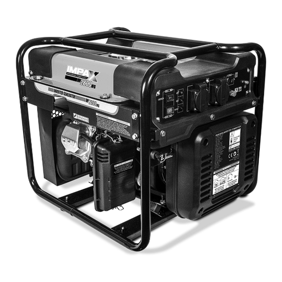
- Page 1 2800W INVERTER GENERATOR IM2800IFG Always Read Instruction Manual Retain for Future Reference...
-
Page 2: Certificate Of Guarantee
CERTIFICATE OF GUARANTEE This product is guaranteed for a period of 1 Year, with effect from the date of purchase and applies only to the original purchaser. This guarantee only applies to defects arising from, defective materials and or faulty workmanship that become evident during the guarantee period only and does not include consumable items. -
Page 3: Important Safety Information
IMPORTANT SAFETY INFORMATION The purpose of safety rules is to attract your Generator exhaust contains high levels of attention to possible dangers. The safety carbon monoxide (CO), a poisonous gas you symbols and the explanations with them, require cannot see or smell. If you can smell the your careful attention and understanding. - Page 4 IMPORTANT SAFETY INFORMATION Do not operate generator when you are tired or To prevent an electric shock, never operate the under the influence of drugs, alcohol, or machine in rain, snow or touch with wet hands. medication. Check the fuel system periodically for leaks. The electrical output load must not exceed the Seals and hoses should be checked for signs of maximum load stated on the rating plate.
- Page 5 IMPORTANT SAFETY INFORMATION For power outages, permanently installed ADDING FUEL stationary generators are better suited for Turn the generator off and let it cool for at least providing back-up power to the home. Even a five minutes before removing the fuel cap. properly connected portable generator can Loosen the cap slowly to relieve pressure in the become overloaded.
-
Page 6: Specific Safety Information
SPECIFIC SAFETY INFORMATION WARNING: When this generator is Check the ventilation hole inside the fuel tank cap used to supply a building wiring for debris. Do not block the vent. system: the generator must be installed Do not smoke when filling the generator with by a qualified electrician and connected to a unleaded fuel. - Page 7 COMPONENTS Component List 8. Air filter cover release latch 1. Oil alert indicator (yellow) 9. Air filter cover 2. AC socket (Left side) 10. Fuel valve 3. Frame 11. Choke knob 4. AC socket (Right side) 12. Engine overload indicator (red) 5.
- Page 8 COMPONENTS Component List 16. Spark plug cap 18. Recoil starter grip 17. Oil filler cap/dipstick...
-
Page 9: Technical Specification
COMPONENTS Component List 19. Fuel cap 22. Spark plug socket 20. Fuel gauge 23. Funnel 21. Screwdriver 24. DC charging leads TECHNICAL SPECIFICATION AC output: 230V~50Hz Fuel type: Unleaded petrol Rated power: 2800W Oil type: SAE 10W-30 Peak power: 3000W Oil capacity: 460ml Rated current:... -
Page 10: Pre-Operation Check
UNPACKING CAUTION! This packaging contains its accessories should be returned together in sharp objects. Take care when their original packaging to the retailer. unpacking. Remove the machine, Do not throw the packaging away, keep it safe together with the accessories supplied, from the throughout the guarantee period, then recycle if packaging. - Page 11 PRE-OPERATION CHECK Remove the fuel cap (Fig.3). Slowly fill the tank with unleaded petrol. The fuel tank should not be filled above the top of the Fig 3 fuel filter (Fig.5). Fig 5 Remove and clean the fuel filter (Fig.4). Replace and secure the fuel cap.
-
Page 12: Understanding The Control Panel
UNDERSTANDING THE CONTROL PANEL This function is applicable to 12V 1. Economy control switch. When turned to the 5. DC socket. battery charging only. ON position the economy control unit controls the engine speed according to the 6. Ground (earth) terminal. (See page 11.) connected load. -
Page 13: Starting The Generator
OPERATING INSTRUCTIONS STARTING THE GENERATOR 4. Hold down the generator firmly with one CAUTION. Always check the oil and hand on the frame. With the other hand grip fuel level before starting the engine, the recoil starter cord handle (Fig.10) and see Page 10 &... - Page 14 OPERATING INSTRUCTIONS ECONOMY CONTROL SWITCH (Fig.12) 1. Before stopping the engine make sure that all the electrical loads are disconnected from Fig 12 the generator AC outlet sockets. 2. Switch off the engine by putting the engine switch in the STOP position (Fig.13). Fig 13 On: Recommended to minimize fuel consumption and further reduce noise levels...
- Page 15 OPERATING INSTRUCTIONS Using a hydrometer measure the specific gravity Fig 16 of the battery fluid and calculate the charging time in accordance with the table shown, Fig 15. Fig 15 NOTE: The DC protector turns off automatically if the current goes above the rated output during battery charging.
-
Page 16: General Maintenance
MAINTENANCE GENERAL MAINTENANCE CHECKING/CLEANING THE AIR FILTER Keep the generator in a clean and dry For proper performance and long life, keep air environment where it is not exposed to dust, filters clean. dirt, moisture, or corrosive vapours. 1. Undo the latches at the top and bottom of Do not allow the cooling air slots in the the air filter cover and remove the cover and generator to become clogged with foreign... - Page 17 MAINTENANCE SPARK PLUG MAINTENANCE 7. Replace spark plug cap. The spark plug must be properly gapped and WARNING! Spark plug must be free of deposits in order to ensure proper engine assembled firmly, or it will become hot operation. To check: and may damage generator.
-
Page 18: Draining The Fuel Tank
MAINTENANCE DRAINING THE FUEL TANK 2. Position an approved fuel container under 1. Turn the engine switch to STOP (O). the carburetor drain screw to catch fuel; Turn the engine switch ON, and loosen the 2. Turn the fuel valve lever to the OFF position. carburetor drain screw (Fig.24). -
Page 19: Maintenance Chart
MAINTENANCE CHART Item Remark Pre-operation Initial 1 month Every 3 month Every 6 month Every 12 month check (daily) or 20hours or 50 hours or 100 hours or 300 hours Spark plug Check condition Adjust gap and clean Replace if required Engine oil Check oil level Replace... -
Page 20: Troubleshooting
TROUBLESHOOTING... -
Page 21: Environmental Protection
TROUBLESHOOTING ENVIRONMENTAL PROTECTION Information for (private householders) for the environmentally responsible disposal of Waste Electrical and Electronic Equipment (WEEE) This symbol on products and or accompanying documents indicates that used and end of life electrical and electronic equipment should not be disposed of in household waste. - Page 22 SYMBOLS Some of the following symbols may be used on this tool. Please study them and learn their meaning. Proper interpretation of these symbols will allow you to operate the tool better and safer. SYMBOLS DESIGNATION/EXPLANATION Do not expose to rain or use in damp locations. To reduce the risk of injury, the user must read and understand the operator’s manual before using this product.
- Page 23 NOTES...
- Page 24 NOTES...
-
Page 25: Ec Declaration Of Conformity
EC DECLARATION OF CONFORMITY Product model: IM2800IFG Name and address of the manufacturer or his authorised representative: NAP BRANDS LTD. Office 20, Fleming Court Business Centre, Leigh Road, Eastleigh, Hampshire SO50 9YN Tel: +44(0)1926 482880. Email: sales@napbrands.co.uk This declaration of conformity is issued under the sole responsibility of the manufacturer. - Page 26 WARNING! DO NOT OVERFILL THIS UNIT WITH OIL FILL WITH 410-460ML OF SAE 10W-30 or 10W-40 4-STROKE ENGINE OIL ONLY. The oil level should fall within the level indicator area on the dipstick. Overfilling this generator with oil will cause serious damage and will invalidate your warranty.
- Page 27 IMPAX GENERATOR TECHNICAL HELPLINE Technical and Spares Support IMPAX Petrol Generator Product Helpline If you experience any problems with your IMPAX generator please contact the helpline who can o er fault-finding, technical support and general guidance. Technical Helpline Number 0344 2642 485...
-
Page 28: Declaration Of Conformity
DECLARATION OF CONFORMITY Product model: IM2800IFG Name and address of the manufacturer or his authorised representative: NAP BRANDS LTD. Office 20, Fleming Court Business Centre, Leigh Road, Eastleigh, Hampshire SO50 9YN Tel: +44 (0)23 8064 9650. Email: sales@napbrands.co.uk This declaration of conformity is issued under the sole responsibility of the manufacturer.
Need help?
Do you have a question about the IM2800IFG and is the answer not in the manual?
Questions and answers