Table of Contents
Advertisement
Advertisement
Table of Contents

Related Manuals for Impax IM1000SIG


Summary of Contents for Impax IM1000SIG
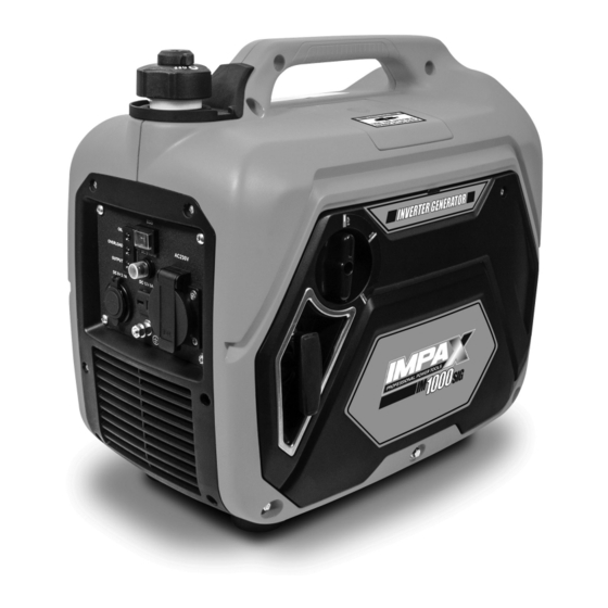
- Page 2 1000W INVERTER GENERATOR IM1000SIG Always Read Instruction Manual Retain for Future Reference...
-
Page 3: Certificate Of Guarantee
CERTIFICATE OF GUARANTEE This product is guaranteed for a period of 1 Year, with effect from the date of purchase and applies only to the original purchaser. This guarantee only applies to defects arising from, defective materials and or faulty workmanship that become evident during the guarantee period only and does not include consumable items. -
Page 4: Important Safety Information
IMPORTANT SAFETY INFORMATION The purpose of safety rules is to attract your Generator exhaust contains high levels of attention to possible dangers. The safety carbon monoxide (CO), a poisonous gas you symbols and the explanations with them, require cannot see or smell. If you can smell the your careful attention and understanding. - Page 5 IMPORTANT SAFETY INFORMATION Do not operate generator when you are tired or To prevent an electric shock, never operate the under the influence of drugs, alcohol, or machine in rain, snow or touch with wet hands. medication. Check the fuel system periodically for leaks. The electrical output load must not exceed the Seals and hoses should be checked for signs of maximum load stated on the rating plate.
-
Page 6: Adding Fuel
IMPORTANT SAFETY INFORMATION For power outages, permanently installed ADDING FUEL stationary generators are better suited for Turn the generator off and let it cool for at least providing back-up power to the home. Even a five minutes before removing the fuel cap. properly connected portable generator can Loosen the cap slowly to relieve pressure in the become overloaded. -
Page 7: Specific Safety Information
SPECIFIC SAFETY INFORMATION WARNING: When this generator is Check the ventilation hole inside the fuel tank cap used to supply a building wiring for debris. Do not block the vent. system: the generator must be installed Do not smoke when filling the generator with by a qualified electrician and connected to a unleaded fuel. - Page 8 COMPONENTS Component List 1. DC circuit breaker 6. AC power output indicator (green) 2. AC socket Overload indicator light (red) 3. Ground (earth) terminal Oil alert indicator (yellow) 4. DC 12V 5A socket 9. Economy control switch 5. 2 x USB DC 5V 2.1A socket...
- Page 9 COMPONENTS Component List 10. Carry handle 13. Spark plug access panel 11. Fuel tank cap air vent knob 14. Recoil starter 12. Fuel tank cap 15. Engine switch Stop/Run/Start...
- Page 10 COMPONENTS Component List 16. Access panel screws 18. Air filter 17. Access panel for Oil filler cap and air filter 19. Oil filler cap/dipstick...
-
Page 11: Technical Specification
COMPONENTS Component List 22. Spark plug socket handle & screwdriver 20. Oil measuring jug 23. Spark plug socket 21. DC battery charging cables 24. Muffler TECHNICAL SPECIFICATION AC output: 230V~50Hz Fuel tank capacity: 2.6L Rated power: COP 1.0kW Fuel type: Unleaded petrol Peak power: MAX 1.05kW... -
Page 12: Pre-Operation Check
UNPACKING CAUTION! This packaging contains its accessories should be returned together in sharp objects. Take care when their original packaging to the retailer. unpacking. Remove the machine, Do not throw the packaging away, keep it safe together with the accessories supplied, from the throughout the guarantee period, then recycle if packaging. -
Page 13: Oxygenated Fuels
PRE-OPERATION CHECK USING FUEL STABILIZER When adding petrol to the generator, make sure Fuel gets old, oxidizes, and breaks down over the unit is sitting on a flat, level surface. If the time. Adding a fuel stabilizer (not included) engine is hot, let the generator cool before extends the usable life of fuel and helps prevent adding fuel. - Page 14 LOCATION AND GROUNDING Before using this generator it must be prepared When placing the spike into the ground the correctly before use. Locate the generator on generator must not be running and it is firm level ground away from buildings or other suggested that the spike is pushed into the structures ensuring that the exhaust is not ground by at least 100mm so that it is firm and...
-
Page 15: Understanding The Control Panel
UNDERSTANDING THE CONTROL PANEL 1. The Oil alert system is designed to prevent 5. Ground (earth) terminal. (See page 13.) engine damage caused by an insufficient 6. 5V USB sockets. Power your smartphone, amount of oil in the crankcase. Before the oil tablet, laptop etc. -
Page 16: Before Operating The Unit
OPERATING INSTRUCTIONS BEFORE OPERATING THE UNIT Fig 7 Only use OUTSIDE and far away from windows, doors, and vents. NEVER use inside a home or garage, even if doors and windows are open. Always position the generator on a flat firm surface. - Page 17 OPERATING INSTRUCTIONS With the switch in the On position, the engine Fig 9 speed is controlled automatically. The engine speed is lowered when the load on the generator is reduced, turned off or disconnected. When loads are turned on or re-connected, the engine returns to the correct speed to power the connected load.
-
Page 18: Stopping The Generator
OPERATING INSTRUCTIONS Suggested Device Maximum Wattage Suggested Wattage Bayonet/Screw in globes (home use) Up to 1750W Max. of 35 x 50W globes Florescent tubes Up to 1200W Max. of 60 x 20W globes Halogen lights Up to 1300W Power tools Up to 1300W Laptop computer Up to 700W... - Page 19 OPERATING INSTRUCTIONS WARNING: While operating and Start the generator. storing, keep at least 3 feet of NOTE: Ensure the Economy switch is turned off clearance on all sides of this product, while charging batteries. including overhead. Allow a minimum of 30 minutes of “cool down”...
- Page 20 OPERATING INSTRUCTIONS If the (Red) overload indicator light illuminates Fig 15 stop the generator and investigate the cause. Before connecting an appliance to the generator, check that it is in good order, and that its electrical rating does not exceed that of the generator.
-
Page 21: High Altitude Operation
OPERATING INSTRUCTIONS HIGH ALTITUDE OPERATION CAUTION: If the carburetor has been Specific modifications are needed for high- modified for high altitude operation, altitude operation. Please contact your the air-fuel mixture will be too lean for authorized service center for important low altitude use. -
Page 22: Engine Oil Replacement
MAINTENANCE Remove the air filter, Fig.19. NOTE: Drain the oil while the engine is still warm but not hot. Warm oil will drain quickly Fig 19 and more completely. WARNING: Do not change engine oil while it is hot. Accidental contact with hot engine oil could result in serious burns. - Page 23 MAINTENANCE FUEL TANK FILTER (FIG 24) Fig 22 Fig 24 Fig 23 After every 100 hours of running or every 6 months the fuel tank filter should be removed and cleaned. Remove the fuel tank filler cap and the filter, clean the filter thoroughly using an environmentally friendly water based degreasing agent and re-fit.
- Page 24 MAINTENANCE TRANSPORTING Fig 25 Place the choke lever in the off position. Make sure engine and exhaust of unit is cool. Keep unit level to prevent fuel spillage. Do not drop or strike unit or place under heavy objects. STORAGE SCREW If the generator is not to be used or is to be stored for more than one month the following...
-
Page 25: Maintenance Chart
MAINTENANCE CHART Item Remark Pre-operation Initial 1 month Every 3 month Every 6 month Every 12 month check (daily) or 20hours or 50 hours or 100 hours or 300 hours Spark plug Check condition Adjust gap and clean Replace if required Engine oil Check oil level Replace... -
Page 26: Troubleshooting
TROUBLESHOOTING... -
Page 27: Environmental Protection
TROUBLESHOOTING CONDITION PROBABLE CAUSE CORRECTIVE ACTION Tripped circuit breaker Reset Poor connection or faulty lead Check and repair Indicator light ON. No AC output Broken recepticle Faulty circuit breaker Check and repair Indicator light OFF. Generator problem No AC output Output power too Engine RPM set too No load speed set... - Page 28 SYMBOLS Some of the following symbols may be used on this tool. Please study them and learn their meaning. Proper interpretation of these symbols will allow you to operate the tool better and safer. SYMBOLS DESIGNATION/EXPLANATION Do not expose to rain or use in damp locations. To reduce the risk of injury, the user must read and understand the operator’s manual before using this product.
- Page 29 NOTES...
-
Page 30: Ec Declaration Of Conformity
EC DECLARATION OF CONFORMITY Product model: IM1000SIG Name and address of the manufacturer or his authorised representative: NAP BRANDS LTD. Office 20, Fleming Court Business Centre, Leigh Road, Eastleigh, Hampshire SO50 9YN Tel: +44(0)1926 482880. Email: sales@napbrands.co.uk This declaration of conformity is issued under the sole responsibility of the manufacturer. - Page 31 WARNING! DO NOT OVERFILL THIS UNIT WITH OIL FILL WITH 150ML OF SAE 10W-30 or 10W-40 4-STROKE ENGINE OIL ONLY. The oil level should fall within the level indicator area on the dipstick. Overfilling this generator with oil will cause serious damage and will invalidate your warranty.
- Page 32 IMPAX GENERATOR TECHNICAL HELPLINE Technical and Spares Support IMPAX Petrol Generator Product Helpline If you experience any problems with your IMPAX generator please contact the helpline who can o er fault-finding, technical support and general guidance. Technical Helpline Number 0344 2642 485...
-
Page 33: Declaration Of Conformity
DECLARATION OF CONFORMITY Product model: IM1000SIG Name and address of the manufacturer or his authorised representative: NAP BRANDS LTD. Office 20, Fleming Court Business Centre, Leigh Road, Eastleigh, Hampshire SO50 9YN Tel: +44 (0)23 8064 9650. Email: sales@napbrands.co.uk This declaration of conformity is issued under the sole responsibility of the manufacturer.
Need help?
Do you have a question about the IM1000SIG and is the answer not in the manual?
Questions and answers