Table of Contents
Advertisement
Quick Links
•
Operator's manual
•
Parts manual
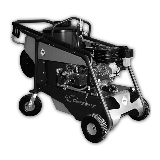
Cold water pressure washer
Hot water pressure washer
Environmental Weed killer
N120-0013
06/11/2012 (REV 1)
Model
MS Gregson
Division de RAD Technologies Inc.
4300, Vachon st.
Drummondville (Qc)
Canada J2B 6V4
Tel.: 819 474-1910
Fax: 819 474-5317
info@msgregson.com
www.msgregson.com
Advertisement
Table of Contents

Related Manuals for MSG Geyser


Summary of Contents for MSG Geyser
- Page 1 • Operator’s manual • Parts manual Cold water pressure washer Hot water pressure washer Environmental Weed killer Model MS Gregson Division de RAD Technologies Inc. 4300, Vachon st. Drummondville (Qc) Canada J2B 6V4 Tel.: 819 474-1910 Fax: 819 474-5317 info@msgregson.com www.msgregson.com N120-0013 06/11/2012 (REV 1)
-
Page 3: Table Of Contents
TABLE OF CONTENTS Specifications ....................... 4 To the purchaser Illustrations ........................5 Limited warranty ......................6 Safety precautions Notice .......................... 7 Before operation ......................7 Pressure washer/weed killer operation ..............7-8 Maintenance ........................ 8 Labels ..........................9 Installation instructions ....................10 Operation instructions Preparation ........................ 11 Filling the fuel tanks .................... -
Page 4: Specifications
SPECIFICATIONS Pressure washer mode General Features specifications Commercial Maximum flow rate 3.5 US gpm (13.2 l/min) Engine Subaru, EX400 Maximum pressure 3500 psi (241 bar) Rotation speed 3450 rpm Engine maximum fuel consumption 0.80 US gph (3.03 l/h) Shaft Solid shaft, 1" Soap injection Low pressure type Fuel tank 1.85 US gal (7.0 l) -
Page 5: Illustrations
TO THE PURCHASER All products are designed to give safe, dependable service if they are operated and maintained according to instructions. Read and understand this manual before operation. This manual has been prepared to assist the owner and operators in the safe operation and suitable maintenance of the hot water pressure washer / thermal weed killer. -
Page 6: Limited Warranty
LIMITED WARRANTY MS Gregson DIV. OF RAD TECHNOLOGIES INC. Pressure washers/weed killers manufactured by are warranted, to the original purchaser, to be free from defects in materials and workmanship for the periods specified below. Normal use conditions, according to the instructions in this manual, apply. This limited warranty is subject to the exclusions listed below, is calculated from the date of delivery to the original purchaser, and applies to the original components only. -
Page 7: Safety Precautions
SAFETY PRECAUTIONS SAFETY FIRST This symbol, the industry’s «Safety Alert Symbol», is used throughout this manual and on labels on the machine itself to warn of the possibility of personal injury. Read these instructions carefully. It is essential that you read the instructions and safety regulations before you attempt to assemble or use this machine. -
Page 8: Maintenance
SAFETY PRECAUTIONS 11. Never operate the pump without water supply. 12. Never let the burner run when the oil tank is empty. 13. Children and pets must be kept away from the area of operation due to a possibility of burns from hot machine components or injury from any equipment. 14. Refuel in a well-ventilated area with the equipment stopped. If any fuel is spilled, clean it up completely and allow vapors to dissipate before starting the machine again. -
Page 9: Labels
LABELS AU-DECAVER8 AU-DECINSGD AU-DECHOT AU-DECAVER3 AU-DECIDJET25 AU-DECMSLOGOE-G AU-DECECOT AU-DECBATTERIE AU-DEC3VDES AU-DECAVER1 AU-DECAVER7 AU-DEC3VDES AU-DECHUILE 000-191 AU-DECFABCANADA AU-PNS7NC-G N120-0013... -
Page 10: Installation Instructions
INSTALLATION INSTRUCTIONS 1. Install the hydraulic straight fitting (A on figure 1) to the reel exit. 2. Install the hydraulic elbow fitting (B on figure 2) to the reel entry. 3. Install the reel to the reel support with 5/16" NC x 3/4" bolts, 5/16" lockwashers and 5/16" flat washers (C, D and E on figure 3). 4. Connect the hose coming from the coil to the hydraulic elbow fitting at the reel entry. 5. Install the storage compartment (F on figure 5) with 5/16" NC x 1" bolts, 5/16" lockwashers and 5/16" flat washers (G, H and I on figure 5). 6. Connect the electric connector located at the end of the burner switch harness. 7. Install the handlle (J on figure 7) with 5/16" NC x 2 1/4" bolts, 5/16" washers and 5/16" nylon locknuts (K, L and M on figure 7). 8. Connect the spray gun hose to the hydraulic straight fitting located at the reel exit. Roll the hose on the reel. -
Page 11: Operation Instructions
OPERATION INSTRUCTIONS Preparation 1. Make sure that all hoses are in good state, not cracked or crushed. 2. Check the oil level of the pump. Pump must be in a level position. Oil level must be halfway on the sight glass (A on figure 1) or visible on the dipstick (B on figure 1). 3. Check the oil level of the engine. Engine must be in a level position. Remove the oil filler cap/ dipstick (C on figure 1). Oil level should be at bottom edge of the oil fill hole. -
Page 12: Starting The Engine
OPERATION INSTRUCTIONS Starting the engine DO NOT START THE ENGINE WITHOUT SUPPLYING WATER TO THE PUMP These instructions will be useful for the following sections and will be referred to as “start the engine”. Starting the engine with the electric starter: 1. Turn down the fuel valve (J on figure 6) to open. -
Page 13: Cold Water Pressure Washing
OPERATION INSTRUCTIONS Cold water pressure washing 1. Fill the fuel tanks (see “Filling the fuel tanks” previous section). 2. Remove the washing nozzle or weed killing tool at the wand outlet (O on figure 7). 3. Connect a water supply hose at the machine inlet (P on figure 7) and open the hose valve. The supply hose flow rate must be at least 4 gpm (15 l/min). 4. Turn the mode selection valve (Q on figure 7) on the side of the machine, to “Washer” position. 5. Depress the gun trigger (R on figure 8) until water flows out limpid and regularly. Release the gun trigger. Figure 7 6. Install a high pressure nozzle (S on figure 8) at the wand outlet (T on figure 9): Yellow = 15° angle, heavy dirt Green = 25° angle, medium dirt White = 40° angle, light dirt or rinse. -
Page 14: Injecting Soap
OPERATION INSTRUCTIONS Injecting soap 1. If the machine is running in hot water pressure washing mode, turn off the burner switch (W on figure 11) and keep water flowing until its temperature is less than 100°F (40°C). 2. Remove the high pressure nozzle at the wand outlet and replace it by the black soap nozzle (X on figure 12). 3. Insert the soap filter and hose (Y on figure 13) in a liquid soap container. 4. Rate of injected soap can be adjusted using the soap valve (Z on figure 13). 5. Depress the gun trigger. Water and soap mix will take 30 seconds to reach the nozzle and flow out. 6. Once soap application is finished, remove the soap nozzle and install a high pressure nozzle to rinse (yellow, green or white). Soap will flow out for 30 seconds and then stop. IMPORTANT: • If corrosive products have been injected, rinse injector by injecting water for a couple of minutes. Weed killing 1. Fill the fuel tanks (see “Filling the fuel tanks” previous section). 2. Remove the washing nozzle or weed killing tool at the wand outlet (AA on figure 14). 3. Connect a water supply hose at the machine inlet (BB on figure 14) and open the hose valve. The supply hose flow rate must be at least 4 gpm (15 l/min). 4. Turn the mode selection valve (CC on figure 14) on the side of the machine, to “Weed killer” position. 5. Depress the gun trigger (DD on figure 15) until water flows out limpid and regularly. Release the gun trigger. 6. Install the weed killing tool (EE on figure 16) at the wand outlet (FF on figure 16). 7. Start the engine according to “Starting the engine” previous section and set the speed to full throttle. 8. Turn on the burner switch (GG on figure 17). - Page 15 OPERATION INSTRUCTIONS Figure 11 Figure 12 Figure 13 Figure 14 Figure 15 Figure 16 Figure 17 Figure 18 Figure 20 Figure 19 N120-0013...
-
Page 16: Stopping Procedure
OPERATION INSTRUCTIONS Stopping procedure 1. If the machine has been used for hot water pressure washing or for weed killing, turn off the burner switch (LL on figure 21). 2. If the machine has been used for soap injecting, install a high pressure yellow, green or white nozzle (MM on figure 22) at wand outlet (NN on figure 22). 3. Depress the gun trigger until water flows out limpid and regularly, and at a temperature of less than 100°F (40°C). -
Page 17: Maintenance
MAINTENANCE Engine oil change The first engine oil change must be done after 10 hours of use. The next oil changes must be done after every 50 hours of use. 1. Place a container under the machine to recover used oil. 2. Unscrew the oil drain plug (A on figure 1). -
Page 18: Battery
MAINTENANCE Battery DISCONNECTED BATTERY: When you receive your high pressure washer/weed killer, the battery has been disconnected to avoid long term discharging. INITIAL START-UP: Recharge the battery to full capacity before connecting it to the machine. Look for the positive wire (G on figure 5) between the engine and the heating coil. Take off the plastic insulator and keep it in the storage compartment for further use. Make sure that the now non-protected connector does not touch grounded metallic parts. -
Page 19: Descaling The Heating Coil
MAINTENANCE WARNING: • The battery contains sulphuric acid. Avoid contact with skin, eyes or cloths. Wear rubber gloves and eyeglasses or visor when handling, filling or recharging the battery. If electrolyte splashes in the eyes or on the skin, rinse with a large quantity of pure water and call a physician immediately. • The battery produces gaseous hydrogen and oxygen while recharging. Keep away all sources of lighting. When checking electrolyte level, use a flashlight or permanent light for lighting. Do not turn on or turn off the lighting source near the battery. Do not smoke or produce sparks. CAUTION: • Always disconnect the battery before recharging. -
Page 20: Storage
MAINTENANCE Storage If the machine is to be stored for a long time, take the following precautions: 1. Winterize the machine. Follow instructions specified at the end of previous section. 2. Using a siphon, empty the engine gas tank. 3. Recirculate antifreeze. Suck antifreeze from the container and return it into the same container. To empty the carburetor, start the engine and let it run until engine stops by itself. -
Page 21: Periodic Maintenance Schedule Table
PERIODIC MAINTENANCE SCHEDULE TABLE Maintenance items Daily Every Every Every Every Every 1000 hours hours hours hours hours Check general condition of the machine • Check engine oil level • Check pump oil level • Check hoses condition • Check water inlet gasket and filter •... -
Page 22: Trouble Shooting Guide
TROUBLE SHOOTING GUIDE FAULT CAUSE REMEDY ENGINE Discharged battery. Charge battery. Check engine charging The engine starter does not work. system. Defective battery. Replace battery. The oil level is too low. The engine oil Add oil in the engine crankcase. Adjust The engine stops and does not restart. -
Page 23: Pump
TROUBLE SHOOTING GUIDE FAULT CAUSE REMEDY PUMP The pump valves are jammed by dirt. Clean the valves. Check or add a filter The motor runs but the pump does not at the pump inlet. work. The O’ rings of the valves are damaged. Replace. -
Page 24: Regulator
TROUBLE SHOOTING GUIDE FAULT CAUSE REMEDY PUMP Bearings are worn. Replace. Noisy pump. Pump is sucking air. Check the supply piping. Water supply is insufficient. Check the supply flow. Inlet water temperature is too high. Lower the inlet water temperature. The pump key is worn. - Page 25 TROUBLE SHOOTING GUIDE FAULT CAUSE REMEDY PRESSURE WASHING PRESSURE REGULATOR Water coming into the soap jar. Clean or repair the soap injector check valve. The regulator engages and releases There is not enough flow to maintain Clean the nozzle (problem encountered when the gun trigger is engaged. the regulator engaged (jammed nozzle).
-
Page 26: Soap Injector
TROUBLE SHOOTING GUIDE FAULT CAUSE REMEDY SOAP INJECTOR Soap does not inject. The soap hose or the soap filter is dirty. Check and clean. The soap nozzle is not installed. Install the soap nozzle. The injector is dirty or jammed. Check and clean. The injector restrictor is worn. - Page 27 TROUBLE SHOOTING GUIDE FAULT CAUSE REMEDY OIL BURNER The water temperature is not sufficient. The water temperature is not Check the weed killing temperature Adjust the weed killing pressure. sufficient. and pressure. The high limit temperature switch is Replace. defective. Lime has built up inside the heating Scale the coil (see maintenance coil.
- Page 28 EXPLODED VIEWS, ASSEMBLY N120-0013...
- Page 29 EXPLODED VIEWS, ASSEMBLY N120-0013...
- Page 30 EXPLODED VIEWS, ASSEMBLY N120-0013...
- Page 31 EXPLODED VIEWS, ASSEMBLY N120-0013...
- Page 32 EXPLODED VIEWS, ASSEMBLY N120-0013...
- Page 33 EXPLODED VIEWS, ASSEMBLY N120-0013...
- Page 34 EXPLODED VIEWS, ASSEMBLY N120-0013...
- Page 35 EXPLODED VIEWS, ASSEMBLY N120-0013...
- Page 36 EXPLODED VIEWS, ASSEMBLY N120-0013...
- Page 37 EXPLODED VIEWS, ASSEMBLY N120-0013...
- Page 38 EXPLODED VIEWS, ASSEMBLY N120-0013...
- Page 39 EXPLODED VIEWS, ASSEMBLY N120-0013...
-
Page 40: Exploded Views, Assembly
EXPLODED VIEWS, ASSEMBLY N120-0013... - Page 41 AU-MV55038 EXPLODED VIEWS, MAIN COMPONENTS AU-MV55038 AU-000125 AU-0115712270 AU-0103710740 AU-0118720120 AU-0104720230 AU-0122790030 AU-0106720390 AU-0128740090 AU-0107720800 AU-0157710040 AU-0107770080 AU-030101 AU-0109712660 AU-030200 AU-0110750170 AU-060109 AU-0110750910 AU-060129 AU-0110751311 AU-150204 AU-0110751321 AU-400305 AU-0112720010 AU-R00000116 AU-0115712250 AU-4079900005 N120-0013...
- Page 42 AU-MV59538 EXPLODED VIEWS, MAIN COMPONENTS AU-MV59538 AU-0109712660 AU-030101 AU-U00000071 AU-000125 AU-0128740090 AU-C00017009 AU-0110750910 AU-4079500001 AU-0107720000 AU-0118720120 AU-0112720010 AU-0112720030 AU-0104720230 AU-R00000151 AU-0117740350 AU-0110750170 AU-0112720100 AU-R00000138 AU-0122790030 AU-0114730010 AU-0107720050 AU-0110751311 AU-0107720080 AU-0110750041 AU-0115712250 AU-0134710000 AU-0125710010 AU-030200 AU-060109 AU-M01700013 AU-0107770080 AU-0157710040 AU-V00100003 AU-150204 AU-0107720800 KIT : AU-4079900005 AU-400305...
- Page 43 EXPLODED VIEWS, MAIN COMPONENTS BK-MS302 BK-MS302 DESCRIPTION BK-5874BK BK-2256 BK-3492BKA AU-X115A BK-3494BK BK-5394 BK-3493 BK-21557 BK-21231U BK-21404 BK-3380 BK-214056 BK-2460 A2VA-7116 BK-51524 BK-21757 A2VA-2116 BK-51304 BK-2184402U A2EA-6520 BK-3616 BK-21767 A2VA-7116, A2VA-2116 BK-AF40XPDC BK-21807 A2EA-6520 BK-366 BK-21441 A2VA-7116 BK-21877 A2VA-2116 BK-21877U A2EA-6520 BK-3666 BK-213...
- Page 44 EXPLODED VIEWS, MAIN COMPONENTS CO-ZWD3540G CO-ZWD3540G REF N TORQUE TORQUE (ft/lb) (Nm) 24.4 50.0 CO-3218/324 CO-2812/38 CO-3202/18 CO-1210/55 CO-3609/156 CO-2409/44 CO-1210/46 CO-3011/14 CO-3009/87 CO-205/50 CO-3604/17 CO-3019/33 CO-1802/177 CO-3201/10 CO-1205/25 CO-1210/333 CO-1210/48 CO-1210/206 CO-3202/269 CO-402/220 CO-3609/88 CO-3609/180 CO-1004/12 CO-3609/32 CO-402/172 CO-2811/98 CO-1210/386 CO-3607/168 CO-3019/11...
-
Page 45: Exploded Views, Main Components
EXPLODED VIEWS, MAIN COMPONENTS JB-12212PP100 JB-12212PP100 JB-2317112PP JB-23173EPR JB-CP231745304S JB-23172PP JB-SRI JB-SRI JB-362596411 JB-922218001 JB-903566001 JB-922200001 JB-362600701 JB-993056001 JB-903825001 JB-362601701 JB-947396001 JB-362602021 JB-927707001 JB-362598661 JB-903578001 JB-903600001 JB-362597701 AU-ST15005 AU-ST15005 AU-020002050 AU-020001910 AU-010001310 AU-201500496 AU-100000400 AU-202000025 AU-100001270 AU-040000031 AU-040000050 AU-060000270 N120-0013... - Page 46 NOTES N120-0013...
- Page 47 NOTES N120-0013...
- Page 48 MS Gregson Division de RAD Technologies Inc. 4300, Vachon st. Drummondville (Qc) Canada J2B 6V4 Tel.: 819 474-1910 Fax: 819 474-5317 info@msgregson.com www.msgregson.com N120-0013...
Need help?
Do you have a question about the Geyser and is the answer not in the manual?
Questions and answers