
Related Manuals for MSG GEYSER G3040EA240


Summary of Contents for MSG GEYSER G3040EA240
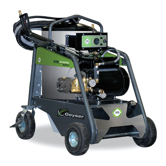
- Page 1 • Operator’s manual • Parts manual Hot water pressure washer Cold water pressure washer GEYSER G3040EA240 Real product may be different from picture.
-
Page 3: Table Of Contents
Table of contents Specifications....................... 4 To the purchaser ..Product.registration....................... 5 Safety precautions ...Description.of.warnings....................6 ...Description.of.safety.symbols.and.hazard.warnings........... 6 ...Warning.labels....................... 7 ...Safety........................8.to.12 Installation instructions..................13 Operation instructions ...Preparation........................14 ...Filling.the.fuel.tank.......................14 ...Cold.water.pressure.washing..................15 ...Hot.water.pressure.washing..................15 ...Injecting.soap.......................16 ...Stopping.procedure.....................17 ...Winterization........................17 Maintenance ...Pump.oil.change......................18 ...Descaling.the.heating.coil................... -
Page 4: Specifications
Specifications Pressure washer mode General Features specifications Use Industrial Maximum flow rate 4.0 US gpm (15.1 l/min) Engine 8 HP, 240 V, 35 A, 1 phase, 60 Hz Maximum pressure 3000 psi (207 bar) Rotation speed 1750 rpm Soap injection Low pressure type Shaft Solid shaft, 1-1/8” Adjustable rate Supply 240 V Activation by dual lance Current 35 A Pressure nozzles 15045, 25045, 40045 Power supply cord 7 m, 8/3 SOOW Soap nozzle 6540 Start & stop Automatic, stop delay Burner exhaust temperature 713°F (378°C) More or less - Pump... -
Page 5: To The Purchaser
To the purchaser All.products.are.designed.to.give.safe,.dependable.service.if.they.are.operated.and.maintained.according.to.instructions..Read and understand this manual before operation. This.manual.has.been.prepared.to.assist.the.owner.and.operators.in.the.safe.operation.and.suitable.maintenance.of.the.hot.water.pres- sure.washer..The.information.is.applicable.to.products.at.the.time.of.manufacture.and.does.not.include.modifications.made.afterwards. Read.and.understand.this.operator’s.manual.before.attempting.to.put.equipment.into.service..Familiarize.yourself.with.the.operating. instructions.and.all.the.safety.recommendations.contained.in.this.manual.and.those.labeled.on.the.equipment..Follow.the.safety.recom- mendations.and.make.sure.that.those.with.whom.you.work.follow.them. Illustrations The.illustrations.may.not.necessarily.reproduce.the.full.detail.and.the.exact.shape.of.the.parts.or.depict.the.actual.models,.but.are. intended.for.reference.only. To assist your dealer in handling your needs, please record hereafter the model number and serial number of your machine. It is also advisable to supply them to your insurance company. It will be helpful in the event that the machine is lost or stolen. Model : Serial number : Date of purchase :... -
Page 6: Description.of.warnings
Safety -Description of warnings The «DANGER» symbol is used to outline a situation where danger is DANGER imminent and must be strictly avoided. Failure to comply could result in serious damage to equipment, personal injury or even death. The« WARNING» symbol describes the potential for danger or impro- WARNING per set up and that should be avoided. -
Page 7: Warning.labels
Safety- Product labels / Warning labels AU-DECG3040EA240 AU-DECFABCANADA AU-DECMSLOGOE-G AU-PNS7NC-G AU-DECGEYSER AU-DECG3040EA240 AU-DECAVER1 AU-DECAVER7 AU-DECHUILE N120-0018A... -
Page 8: Safety
Safety - Before you get started/Machine Precautions WARNING • Read and understand the pressure washer manual before using it. Know how to operate all controls and how to stop the unit. Lack of knowledge can lead to accidents. • Use with CAUTION. High pressure spray can cause serious bodily injury. - Page 9 Safety – Precautions Ventilation and Fire WARNING This product is designed to be used outdoors. NEVER operate this unit in an enclosed area even if the windows are open. • Running the burner gives off carbon monoxide, an odorless, colorless, poison gas. Breathing carbon monoxide can cause headache, fatigue, dizziness, vomiting, confusion, seizure, nausea, fainting or death. • Ensure that exhaust gas cannot enter confined area through windows, doors, ventilation intakes, or other openings.
- Page 10 Safety – Precautions High Pressure Stream/Slippery Surfaces WARNING High velocity spray fluids can penetrate skin, causing serious injury. In the event that an accident occurs and spray appears to have penetrated the skin, SEEK EMERGENCY MEDICAL ATTENTION. DO NOT treat water penetration into the skin as a simple cut. If cleaning and/or soaping agents are being used, advise the physician of the exact type. DO NOT allow CHILDREN or teenagers to operate pressure washer. NEVER aim spray gun at people, animals, or plants. • ALWAYS point spray gun in safe direction and squeeze spray gun trigger, to release high pressure, every time you stop the washer. •...
- Page 11 Safety – Precautions Protective Gear/Kick Back / Electrical Shock WARNING Risk of eye injury. High pressure spray can propel loose stones or objects at high velocity. • Always wear safety goggles and protective clothing when using this equipment or in vicinity of where equipment is in use. • Before starting the pressure washer, be sure you are wearing adequate safety apparel, goggles, boots, gloves and work clothing. •...
- Page 12 Safety – Precautions Hot Surfaces/Important Notices IMPORTANT • If you have questions about intended use, ask dealer or contact the nearest authorized servicing dealer. • STAY ALERT when using a pressure washer. • DO NOT operate when fatigued or under the influence of alcohol or drugs or medications that make restrictions about operating equipment.
-
Page 13: Installation Instructions
Installation Instructions Handle installation 1.. Install.the.handlle.(A.on.figure.1).with.5/16".NC.x.2.1/4".bolts,.5/16". washers.and.5/16".nylon.locknuts.(B,.C.and.D.on.figure.1). Storage compartment installation (optional) 1.. Install.the.storage.compartment.(E.on.figure.2).with.5/16".NC.x.1".bolts. and.5/16".flat.washers.(F.and.G.on.figure.2). Hose reel installation (optional) 1.. Install.the.hydraulic.straight.fitting.(H.on.figure.3).to.the.reel.exit. 2.. Install.the.hydraulic.elbow.fitting.(I.on.figure.4).to.the.reel.entry. 3.. Install.the.reel.to.the.reel.support.with.5/16".NC.x.3/4".bolts,.5/16". Figure 1 lockwashers.and.5/16".flat.washers.(J,.K.and.L.on.figure.5). 4.. Connect.the.short.hose.to.the.hydraulic.elbow.fitting.at.the.reel.entry. (M.on.figure.4). 5.. Remove.the.twist.coupler.from.the.machine.outlet.-.(N.on.figure.6.not. visible) 6.. Install.the.male-female.elbow.at.the.machine.outlet.(O.on.figure.6) 7.. Install.the.swivelling.male-female.elbow.at.the.outlet.of.the.previous. elbow.(P.on.figure.6) 8.. Connect.the.short.hose.to.that.last.elbow.(Q.on.figure.6) 9.. -
Page 14: Operation Instructions
Operation instructions Preparation 1.. Make.sure.that.all.hoses.are.in.good.state,.not.cracked.or.crushed. 2.. Check.the.oil.level.of.the.pump..Pump.must.be.in.a.level.position..Oil.level.must. be.halfway.on.the.sight.glass.(A.on.figure.7).or.visible.on.the.dipstick.(B.on.figure.7). 3.. Check.the.presence.and.state.of.the.water.inlet.gasket.(D.on.figure.8). 4.. Check.the.water.inlet.filter..Unscrew.the.bowl.(E.on.figure.8).and.rinse.if.needed.. Remove.and.clean.the.filter.screen.(F.on.figure.9)..Put.back.in.place.the.screen. and.bowl. 5.. Check.the.state.of.the.fuel.oil.filter.(G.on.figure.10)..Replace.the.filter.if.it.is. Figure 7 damaged.or.dirty. WARNING:.to.avoid.injuries.: •. Before.inspecting,.cleaning,.or.repairing,.make.sure.the.machine.is.parked.on.a. flat.level.surface,.with.wheel.brake.on. •. Risk.of.injection;.always.put.the.safety-catch.on.the.gun.as.soon.as.the.gun.is. not.used,.and.especially.for.replacement.of.nozzles. •. Always.wear.long.clothes,.gloves.and.safety.glasses.when.inspecting,.cleaning,. repairing.and.operating.this.machine. Figure 8 Filling the fuel tank 1.. Remove.the.cap.(I.on.figure.11).from.the.oil.tank. 2.. Fill.with.#2.furnace.oil.(or.lighter).or.diesel..Do.not.overfill..Do.not.fill.the.collar.of. the.tank..Do.not.use.gasoline,.crankcase.draining.or.oil.containing.gasoline.or. solvents. 3.. -
Page 15: Cold.water.pressure.washing
Operation instructions Cold water pressure washing 1.. Connect.a.water.supply.hose.to.the.pump.inlet.(P.on.figure.12).and.open.the.hose. valve..The.supply.hose.flow.rate.must.exceed.the.pump.flow.rate.and.the.pressure. must.be.at.least.30.psi.but.must.not.exceed.80.psi. 2.. Depress.the.gun.trigger.(R.on.figure.14).until.water.flows.out.limpid.and.regularly.. Release.the.gun.trigger. 3.. Install.a.high.pressure.nozzle.(S.on.figure.13).at.the.wand.outlet.(T.on.figure.14): Yellow.=.15°.angle,.heavy.dirt Green.=.25°.angle,.medium.dirt Figure 12 White.=.40°.angle,.light.dirt.or.rinse. 4.. Connect.the.attachment.plug.to.a.proper.electrical.source..Circuit.breaker.for.this. source.should.match.with.the.washer.nominal.current..If.an.extension.cord.is. used,.it.should.be.the.same.size.as.the.washer.power.cord.or.larger.if.washer.cord. and.extension.cord.total.length.exceeds.35.ft..Turn.pump.switch. (W.in.figure.16).to.cold.water.position. 5.. Depress.the.gun.trigger.(R.on.figure.14).to.start.the.pump.motor. 6.. Set.the.lance.to.«rinse».position.(see.soap.injection.part.below) 7.. Press.the.gun.trigger.and.wash..Operate.the.gun.continuously..Do.not.press.and. release.the.trigger.in.cycles.of.less.than.5.seconds. 8.. Pressure.can.be.adjusted.by.means.of.the.high.pressure.regulator.(U.on.figure.15). Figure 13 up.to.3000.psi..Pressure.is.read.on.the.pressure.gauge.(V.on.figure.15). 9.. To.stop,.see.section.“Stopping.procedure”.further.in.this.manual.. 10.. The.washer.is.equipped.with.an.automatic.start/stop.control,.it.should.start. once.the.gun.in.triggered.and.stop.30.seconds.after.the.gun.trigger.has.been released. -
Page 16: Injecting.soap
Operation instructions Injecting soap 1.. To.inject.soap,.unscrew.the.dual.lance.handle.(X.on.figure.17). 2.. Insert.the.soap.filter.and.hose.(Y.on.figure.18).in.a.liquid.soap.container. 3.. Rate.of.injected.soap.can.be.adjusted.using.the.soap.valve.(Z.on.figure.18). 4.. Depress.the.gun.trigger..Water.and.soap.mix.will.take.30.seconds.to.reach.the.nozzle.and.flow.out. 5.. Once.the.soap.application.is.finished..Screw.the.dual.lance.handle.(X.on.figure.17)..Soap.will.flow.out.for.30.seconds.and.the.stop. IMPORTANT: •. If.corrosive.products.have.been.injected,.rinse.injector.by.injecting.water.for.a.couple.of.minutes. Figure 17 Figure 18 N120-0018A... -
Page 17: Stopping.procedure
Operation instructions Stopping procedure 1.. If.the.machine.has.been.used.for.hot.water.pressure.washing,.turn.off.the. burner.switch.(W.on.figure.19). 2.. If.the.machine.has.been.used.for.soap.injecting,.screw.back.the.dual. lance.handle. 3.. Depress.the.gun.trigger.until.water.flows.out.limpid.and.regularly,.and.at.a. temperature.of.less.than.100°F.(40°C). 4.. Release.the.gun.trigger. 5.. Stop.the.pump.motor.(W.in.figure.19) 6.. Close.the.water.supply.valve. 7.. Depress.the.gun.trigger.to.release.pressure.from.the.system. 8.. Disconnect.the.water.supply.hose. 9.. Make.sure.that.all.nozzles,.gun.and.wand.are.stored.in.their. proper.place. Figure 19 10.. Make.sure.that.all.safety.equipment.is.stored.in.its.proper.place. Winterization During winter and cold periods, if there is a freezing risk for the machine, it is recommended to take the following precautions immediately after stopping the machine: 1.. -
Page 18: Maintenance
Maintenance Pump oil change The first pump oil change must be done after 10 hours of use. The next oil changes must be done after every 200 hours of use. 1.. Place.a.container.under.the.pump.to.recover.used.oil. 2.. Unscrew.the.oil.drain.plug.(C.on.figure.21). 3.. Let.oil.flow.slowly.to.avoid.splash. 4.. When.pump.crankcase.is.empty,.screw.back.the.drain.plug. 5.. Unscrew.the.oil.filler.cap/dipstick.(D.on.figure.22). 6.. -
Page 19: Descaling.the.heating.coil
Maintenance Descaling the heating coil Periodically check for possible lime formation into the water circuit. If necessary, proceed as follow: 1.. Use.a.container.that.can.contain.at.least.5.gallons.(20.liters).and.pour.in.water.and.a.special.scaling.acid.solution.like.the. MS-DETAR6K,.following.the.manufacturer.recommended.mixing. 2.. Install.a.5.ft.x.½".of.inside.diameter.(1.5.m.x.13.mm).hose.at.pump.inlet;.put.the.free.end.of.the.5.ft.hose.into.the.container..Remove. the.nozzle.at.the.wand.outlet.and.put.the.wand.in.that.same.container. 3.. Close.the.metering.valve.on.the.soap.injector. 4.. Start.the.motor..DO.NOT.TURN.THE.BURNER.ON..Depress.the.gun.trigger..Let.the.solution.circulate. into.the.system.for.approximately.one.hour.or.until.the.layer.of.lime.has.dissolved..As.hard.water.neutralizes.acid,.in.extreme.cases .you.may.have.to.change.the.solution.during.the.treatment. 5.. When.the.operation.is.completed: -.Stop.the.motor. -.Clean.the.pump.inlet.filter. -.Connect.a.water.supply.hose.to.the.machine.inlet. -.Start.the.motor.and.depress.the.gun.trigger. -.Run.the.machine.until.water.flows.out.limpid.and.regularly. -.Release.the.gun.trigger.and.stop.the.motor. IMPORTANT: To.prevent.possible.damages,.avoid.splashing.or.spilling.solution.on.the.machine.or.its.components.during.the.scaling.operation. -
Page 20: Periodic Maintenance Schedule Table
Periodic maintenance schedule table Maintenance items Daily Every Every Every Every Every 1000 hours hours hours hours hours Check general condition of the machine • Check pump oil level • Check hoses condition • Check water inlet gasket and filter • Check fuel oil filter condition •... -
Page 21: Trouble Shooting Guide
Trouble shooting guide FAULT CAUSE REMEDY MOTOR The motor does not start, The motor has no power supply. Verify plug, power cord, connections, fuses, nothing happens. circuit breaker, switch, thermal protector (reset). The motor makes noise but The pump is frozen. Let the pump heat. does not start. The pump is jammed. Turn the motor manually by the fan. Motor is defective Check capacitors; have the motor repaired. The fan is rubbing against its cover. Repair embossment of the cover. The motor runs but is noisy. The motor or pump bearings are worn. Replace. The motor rotor is unbalanced. Have the motor repaired. The centrifugal switch does not disengage. Repair the switch. The key of the pump is worn. Replace the key. The motor stops. The motor thermal protector has tripped. Let the motor cool and reset the protector. Verify power supply. The attachment plug is unplugged. Plug it back. N120-0018A... -
Page 22: Pump
Trouble shooting guide FAULT CAUSE REMEDY PUMP The motor runs but the pump does not work. The pump valves are jammed by dirt. Clean the valves. Check or add a filter at the pump inlet. The O’ rings of the valves are damaged. Replace. The pump key is broken. Replace. The pump runs, but does not give maximum The nozzle is worn or has not the proper size. Check for the recommended size or replace. pressure. The reading of the gauge is wrong. Replace the gauge. Water flows out from the soap nozzle. Screw or repair the dual lance handle. Leaks in the high pressure line. Stop the leaks. The seat or the valve of the regulator are Check, clean or replace the defective parts. dirty or worn. The pump valves are worn or dirty. Clean or replace. Pump water seals are worn. Replace. Pump is sucking air. Check the supply piping. Water supply is insufficient. Check if supply flow provides the pump’s needs. Fluctuating pressure. Valves are worn or dirty. Clean or replace. Water seals are worn. Replace. Pump is sucking air. - Page 23 Trouble shooting guide FAULT CAUSE REMEDY PUMP Noisy pump. Bearings are worn. Replace. Pump is sucking air. Check the supply piping. Water supply is insufficient. Check the supply flow. Inlet water temperature is too high. Lower the inlet water temperature. The pump key is worn. Replace. Presence of water in oil (white oil). Pump water seals are worn. Replace. High humidity in the air. Increase the oil change frequency. Cleaning of the pump with the nozzle. Never direct the jet toward the machine. Oil dripping under the pump. Crankshaft oil seal broken or worn. Replace. Piston guide scratched or worn. Replace. Piston guide oil seal broken or worn. Replace. Air vent jammed. Clean. Air vent replaced by a non-ventilated cap. Put the origin parts back. Water dripping between pump head and Pump water seals are worn. Replace. crankcase. N120-0018A...
-
Page 24: Regulator
Trouble shooting guide FAULT CAUSE REMEDY PRESSURE REGULATOR The regulator engages and releases when The gun does not properly close. Adjust, repair or replace the gun. the gun trigger is released. Leaks on the high pressure line. Stop the leaks. The regulator check valve does not properly Replace the defective parts. close. The regulator piston seal kit is worn. Replace the defective parts. The regulator guide seal kit is worn. Replace the defective parts. Water coming into the soap jar. Clean or repair the soap injector check valve. The regulator engages and releases when the There is not enough flow to maintain the Clean the nozzle (problem encountered with gun trigger is engaged. regulator engaged (jammed nozzle). interchangeable nozzles). Pump staying under pressure when the gun The gun does not properly close. Repair the gun. is released. The regulator check valve does not close. Repair the check valve. Water dripping from the regulator guide. The regulator guide seal kit is worn. Replace the defective parts. N120-0018A... -
Page 25: Soap.injector
Trouble shooting guide FAULT CAUSE REMEDY SOAP INJECTOR Soap does not inject. The soap hose or the soap filter is dirty. Check and clean. The lance is not in low pressure mode. Put the lance in low pressure mode. The injector is dirty or jammed. Check and clean. The injector restrictor is worn. Replace. The pressure hose is damaged or has a too Replace with a new hose of the right size. small inside diameter. The pressure hose is too long. Try with the original hose. The gun does not open enough. Adjust the gun piston. The soap nozzle is dirty or damaged. Clean or replace. Water flows out from the soap filter. The injector check valve is dirty or worn. Clean or replace. FAULT CAUSE REMEDY OIL BURNER The burner produces white smoke. Presence of water into the oil tank. Empty and clean the tank. Fill with clean oil. The tank is almost empty. Fill the tank. The electrovalve is defective. Repair or replace. The burner produces black smoke. Oil pressure is incorrect. - Page 26 Trouble shooting guide FAULT CAUSE REMEDY OIL BURNER The water temperature is not The thermostat is set too low. Set to desired temperature. sufficient. Lime has built up inside the heating Scale the coil (see maintenance coil. section). Thermostat is defective. Replace. Several times, the burner runs for a few The oil filter is dirty. Replace. minutes, then stops. The coupling between the motor and Replace. the oil pump is damaged. The burner continues to heat when the The pressure switch is defective. Repair or replace. gun trigger is released. The electrovalve is defective. Replace. The burner extinguishes or refuses to The oil tank is empty. Fill the tank. light. The oil filter is blocked. Replace. The oil nozzle is blocked. Replace. The oil pump is defective. Repair or replace. The electrovalve is defective. Replace.
-
Page 27: Automatic.start.&.Stop
Trouble shooting guide FAULT CAUSE REMEDY AUTOMATIC START & STOP The motor does not start, nothing happens The washer is not commected. Connect the washer. The switch is in «OFF» position. Turn «ON» the switch. The washer has no power supply. Verify: circuit breaker, fuse, cord, connec- tions, etc. The control fuse has blown. Replace. The flow switch is defective. Repair or replace. The timer is defective. Replace. The 24 V tranformer is defective. Replace. Replace. The magnetic contactor is defective. The motor does not start, but a «click» is The motor thermal protector has tripped. Reset. heard in the control box. The motor hums but does not start. See MOTOR section. See MOTOR section. The motor does not stop. The flow switch is defective. Repair or replace. The timer is defective. Replace. The magnetic contactor is defective. Replace. N120-0018A... -
Page 28: Exploded.views,.Assembly
Exploded views, assembly N120-0018A... - Page 29 Exploded views, assembly N120-0018A...
- Page 30 Exploded views, assembly N120-0018A...
- Page 31 Exploded views, assembly N120-0018A...
- Page 32 Exploded views, assembly N120-0018A...
- Page 33 Exploded views, assembly N120-0018A...
- Page 34 Exploded views, assembly N120-0018A...
- Page 35 Exploded views, assembly N120-0018A...
- Page 36 Exploded views, assembly N120-0018A...
- Page 37 Exploded views, assembly N120-0018A...
- Page 38 Exploded views, assembly N120-0018A...
- Page 39 Exploded views, assembly N120-0018A...
- Page 40 Exploded views, assembly N120-0018A...
- Page 41 Exploded views, assembly N120-0018A...
- Page 42 Exploded views, assembly N120-0018A...
- Page 43 Exploded views, assembly N120-0018A...
- Page 44 Exploded views, assembly N120-0018A...
- Page 45 Exploded views, assembly Pompe • Pump CO-RWS4030E, CO-RWS3530E, CO-RWS3030E CO-RWS4030E CO-RWS3530E CO-RWS3030E Débit : 4.0 gal/min Débit : 3.6 gal/min Débit : 3.0 gal/min Pression : 3000 lb/po Pression : 3000 lb/po Pression : 3000 lb/po Vitesse : 1750 r/min Vitesse : 1750 r/min Vitesse : 1750 r/min...
- Page 46 Exploded views, assembly CO-RF55NV Régulateur • Regulator REF N° DESCRIPTION CO-1817/95 Knob CO-2803/645 Hose adaptor CO-1210/564 O-ring CO-1802/344 Spring CO-2803/644 Valve adaptor CO-2812/67 Valve seat CO-3003/26 Ball CO-1802/180 Spring CO-424/433 Injector body CO-1210/708 O-ring CO-3410/365 Injector nozzle CO-1802/290 Spring CO-3600/115 Check valve CO-1209/141 Washer CO-424/504...
- Page 47 Exploded views, assembly AU-ST15005 Pistolet • Gun Débit : 10.4 gal/min Pression : 5000 lb/po Température : 300°F Entrée : 3/8" FNPT Sortie : 1/4" FNPT Flow rate : 10.4 GPM Pressure : 5000 PSI Temperature : 300°F Inlet : 3/8" FNPT Outlet : 1/4"...
- Page 48 Exploded views, assembly Lance double • Dual lance AU-ST54 Longueur : 38 po Pression : 4000 lb/po Length : 38" Pressure : 4000 PSI Avant • Before 99-08 REF Nº DESCRIPTION AU-070000330 1/4" NPT Insulated tube AU-010002566 Adaptor AU-050000460 O-ring AU-010002561 Shutter AU-010002562 AU-100001485 Steel handle...
- Page 49 Exploded views, assembly Brûleur • Burner BK-MS202 Nº DESCRIPTION Nº DESCRIPTION BK-5874BK Housing BK-2256 Male-male elbow for fuel tube BK-3492BKA Air band AU-X115A Male-female elbow for pressure gauge (2) BK-3709BK Air shutter BK-5394 Connector tube assembly BK-3493 Escutcheon plate BK-21174 240 V motor BK-21231U Air guide BK-2999...
- Page 50 Exploded views, assembly N120-0018A...
- Page 51 Exploded views, assembly AU-ST44, AU-ST44F Pivot • Swivel REF Nº DESCRIPTION Débit : 26.4 gal/min Pression : 5800 lb/po AU-010004500 Hand wheel, complete Température : 300°F AU-040001720 Pressure washer AU-020003370 Roller holder Flow rate : 26.4 GPM AU-060000900 S. steel ball Pressure : 5800 PSI AU-050001520 O-ring...
- Page 52 Exploded views, assembly Interrupteur à débit • Flow switch MS-ST525 Débit : 12 gal/min Pression : 3500 lb/po Contact à : 0.25 gal/min Flow rate : 12 GPM Pressure : 3500 PSI Contact at : 0.25 GPM REF Nº DESCRIPTION AU-200005511 Complete reed switch AU-020001200 Plastic housing AU-040000720...
-
Page 53: Limited.warranty
Limited warranty Pressure.washers.manufactured.by.MS Gregson Inc..are.warranted,.to.the.original.purchaser,.to.be.free.from.defects.in.materials.and.workmanship.for. the.periods.specified.below..Normal.use.conditions,.according.to.the.instructions.in.this.manual,.apply..This.limited.warranty.is.subject.to.the.exclusions. listed.below,.is.calculated.from.the.date.of.delivery.to.the.original.purchaser,.and.applies.to.the.original.components.only..Parts.replaced.under.this. warranty.will.assume.the.remainder.of.the.corresponding.part’s.warranty.period. 5 YEAR* PARTS, 1 YEAR LABOUR WARRANTY Metallic.components.manufactured.by.MS Gregson Inc.,.such.as.frames,.handles,.guards,.protective.gratings.and.plates,.covers,.and.also.heating. coils**,.have.a.5.year.warranty. *Pumps.are.warranted.for.2.years.by.the.pumps.manufacturer..Manufacturer’s.warranty.does.not.apply.to.freight.damage,.to.freezing.damage,.to. damage.caused.by.replacement.parts.others.than.the.manufacturer’s.ones,.to.normal.wear.of.moving.parts.or.components.affected.by.moving.parts. **The.heating.coils.are.protected.by.a.5.year.pro.rated.warranty.to.the.original.purchaser.upon.the.following.decreasing.scale: •. Full.replacement.or.repair.during.the.first.2.years. •. Replacement.or.repair.with.customer.bearing.40%.of.cost.during.the.third.year. •. Replacement.or.repair.with.customer.bearing.60%.of.cost.during.the.fourth.year. •. Replacement.or.repair.with.customer.bearing.80%.of.cost.during.the.fifth.year. 1 YEAR PARTS, 1 YEAR LABOUR WARRANTY The.other.components,.excluding.accessories.listed.below.and.normal.wear.items.listed.below.are.warranted.for.1.year.on.parts.and.labour. 30 DAY ACCESSORIES WARRANTY Accessories.such.as.discharge.hoses,.quick.couplers,.swivels,.guns,.lances,.nozzles,.pressure.gauges,.thermal.protectors,.and.options.are.warranted. - Page 54 Notes N120-0018A...
- Page 56 MS Gregson Inc. 4300,.Vachon.st. Drummondville.(Qc) Canada.J2B.6V4 Tel.:.819.474-1910 Fax:.819.474-5317 info@msgregson.com www.msgregson.com N120-0018A...
Need help?
Do you have a question about the GEYSER G3040EA240 and is the answer not in the manual?
Questions and answers