Table of Contents
Advertisement
Quick Links
Advertisement
Table of Contents

Related Manuals for ECM miniPEMS2


Summary of Contents for ECM miniPEMS2
- Page 1 Portable Emissions Monitoring System Instruction Manual 9/1/20...
- Page 2 COPYRIGHT 2020 by ECM: ENGINE CONTROL AND MONITORING. All Rights Reserved. No part of this manual may be photocopied or reproduced in any form without prior written consent from ECM: ENGINE CONTROL AND MONITORING. Information and specifications subject to change without notice.
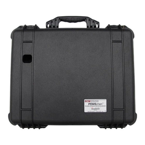
- Page 3 Ceramic exhaust sensors are smaller, more rugged, and faster responding than classical gas analyzers. miniPEMS2 hardware consists of an instrumentation package stored in a 535 mm x 445 mm x 222 mm case. Fully loaded, the case weighs 13 kg. This package consists of: 1.
- Page 4 Data Storage/Communication Device Measurement Modules (logger/CAN adapter) (maximum of 7) 20A Fuse Four 12V Batteries Power Switch Box (one in each corner) Remote “Power to Logger” Switch Battery Charger “100%” light...
- Page 5 Remote “Power to Logger” Switch OBD Connector gpsCAN (roof mount) External Power Cable...
-
Page 6: Quick Start
(software), Setup (hardware), Data Collection, and Data Uploading. Setup (software) Prior to shipping, miniPEMS2 is set up in a manner that should work fine for most testing. It is recommended that you start with this default setup. However, should you want to set up miniPEMS2 yourself, proceed as follows: i. - Page 7 Double click on the ECM logo on the PC. This opens the “Configuration Tool”. The screen should appear as shown below. Note that we are working on the “Modules” tab. There are five groupings of activities: “CAN Adapter”, “Configuration”, “Data for Node ID”, “Tools”, and “Set Module Mode”.
- Page 8 “Setup miniPEMS” button in the “Tools” panel. This will bring you to the following screen. If your miniPEMS2 does not have the obdCAN option, click on the “Apply” button. This will download to the logger’s SD card a file (mpems.dbc) that will be used to translate recorded data.
- Page 9 After clicking “Apply”, click “STOP” in the Configuration Tool, turn the “System Power” switch in the miniPEMS2 off, disconnect the logger from the PC, and wrap the USB cable inside miniPEMS2. If your miniPEMS2 has the obdCAN option and you want to record vehicle datastream information, select “Log Vehicle OBD on Ch2”, click on the “Get...
- Page 10 Connections to measurement modules come through the big rectangular opening in the back/ bottom of the miniPEMS2 case. Connections to the Power to Logger Switch, the GPS antenna, the OBD connector, and the optional external power connection come through the round opening near the handle in the front/top of the case.
- Page 11 The connections to the modules inside miniPEMS2 are made via yellow-tipped, screw-on 12mm Eurofast connectors. The modules are held together as an assembly by two threaded rods (1/4”-20), spacers, two springs, and six nuts. There are two lengths of spacers, the longer one (20.7 mm) is used to space one module from another, and the shorter one (13.3...
- Page 12 When charging, both switches on the Control Switch Box must be off (i.e. you cannot use the miniPEMS2 while charging). With a full charge, you will get “29 hours of use per heated sensor”. Some of the exhaust sensors are heated (NOx, NH3, Lambda, CO/CO2) and some are not.
- Page 13 The logger can be removed from miniPEMS2 and brought to a computer for extracting the data. If it remains attached to miniPEMS2, turn off both the “Power to Logger” and “System Power” switches off, connect the logger to the PC, and double click on the ECM logo. Do not click on “START”.
-
Page 14: Other Information
250 kbps and each of the modules must communicate at that rate. gpsCAN is fixed at this rate but other ECM modules are programmable for rate. If a particular module cannot be “seen” by the software, its baud rate or NID (Node ID) should be checked when just that module is attached to miniPEMS2. - Page 15 2. If the Configuration Tool “locks up”, exit the program and restart it 3. Contact our technical support if you have a problem. Contact all us at 408-734-3433 between 10am and 6pm PST (we’re in California, USA) or at support@ecm-co.com.
-
Page 16: Safety Warnings
Operate the engine only in a well ventilated area and never when you or one of your co- workers is tired. When operating miniPEMS2 in a moving vehicle, the operator should keep his or her eyes on the road. One measure of professionalism is how much you and your co-workers can accomplish... -
Page 17: Warranty And Disclaimers
Warranty and Disclaimers WARRANTY The products described in this manual, with the exception of the sensors, are warranted to be free from defects in material and workmanship for a period of 365 days from the date of shipment to the buyer. Within the 365 day warranty period, we shall at our option repair such items or reimburse the customer the original price of such items which are returned to us with shipping charges prepaid and which are determined by us to be defective. -
Page 18: Engine Control
5191 Lafayette St. Santa Clara, CA, 95054 AND MONITORING Phone: (408) 734-3433 FAX: (408) 734-3432 Email: sales@ecm-co.com Web: www.ecm-co.com EC DECLARATION OF CONFORMITY We declare under our sole responsibility that the products: miniPEMS2 miniPEMS PEMSchen NOx 5210 Analyzer Lambda 5220 Analyzer... - Page 20 Los Altos, CA 94023-0040 USA (408) 734-3433 Fax: (408) 734-3432 www.ecm-co.com...
Need help?
Do you have a question about the miniPEMS2 and is the answer not in the manual?
Questions and answers