Table of Contents
Advertisement
Quick Links
Advertisement
Table of Contents

Subscribe to Our Youtube Channel
Related Manuals for ECM Lambda 5220


Summary of Contents for ECM Lambda 5220
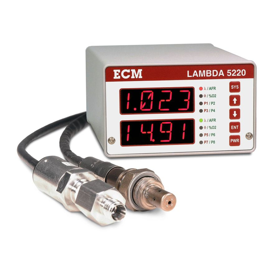
- Page 1 Lambda 5220 Single/Dual Lambda Analyzer Instruction Manual 9/1/14...
- Page 2 COPYRIGHT 2007, 2014 by ECM: ENGINE CONTROL AND MONITORING. All Rights Reserved. No part of this manual may be photocopied or reproduced in any form without prior written consent from ECM: ENGINE CONTROL AND MONITORING. Information and specifications subject to change without notice.
-
Page 3: Table Of Contents
D. Calculating the %O in Air E. LOCKing and unLOCKing Display Head F. Using the Configuration Software G. Setting up ETAS INCA for ECM Analyzers H. Setting up ATI Vision for ECM Analyzers I. Using the Lambda (O ) Sensor Simulator... -
Page 5: Introduction
Introduction The Lambda 5220 The Lambda 5220 is a powerful, “next generation” wideband lambda and O analyzer that packs the following features into a small and easy-to-use package: Single or dual channel lambda sensor operation Lambda 5220 systems can be linked together for multi-cylinder monitoring ... -
Page 6: Lambda 5220 Kit Contents
Lambda 5220 Kit Contents The following items are included with a single-channel, Lambda 5220 kit: Item No. Description Part Number Lambda 5220 Display Head 01-02 LambdaCAN Module, or 02-01 LambdaCANp Module 02-08 Lambda Sensor, NTK 6 ma, or 05-01 Lambda Sensor, Bosch LSU 4.2, or 05-02 Lambda Sensor, Bosch LSU 4.9, or... - Page 7 Lambda Sensor, Bosch LSU 4.2, or 05-02 Lambda Sensor, Bosch LSU 4.9, or 05-03 Lambda Sensor, NTK 4 ma, or 05-04 Others available, contact ECM Eurofast 12mm Cable, 2 m 09-02 Flexi-Eurofast 12mm Cable, 0.3 m 09-04 Eurofast “T” 09-05...
-
Page 8: How To Use
100 m. The Lambda 5220 can be turned on and off by the PWR button on the front of the display head or by a voltage signal (2.7 - 32 V) applied to the KEY connector on the back of the display head. - Page 9 EIB with Power Entry at Module End Connect Connect Power Entry Module EIB Connector Display Head Connect Lambda Sensor Pressure Sensor Figure 1: Lambda 5220 with Power Entry at Module End...
- Page 10 EIB with Power Entry at Display Head End Connect Module Power Entry EIB Connector Display Head Lambda Sensor Pressure Sensor Figure 2: Lambda 5220 with Power Entry at Display Head End...
- Page 11 Resistor Cable P/N 09-04. 0.3 m Flexi-Eurofast Cable P/N 01-02 P/N 04-01 P/N 11-16 P/N 02-01 Lambda 5220 AC/DC Power Supply, DC Power Cable, LambdaCAN Module Display Head Universal, 24 V Banana Plugs (shown), or P/N 11-15 (Spades) P/N 02-08...
- Page 12 CAN Bus P/N 13-01, Manuals and Flexi-Eurofast Connector Configuration Tool Cable P/N 01-02 Connector Lambda 5220 Display Head P/N 12-01 19” Rackmount Panel Figure 4a: Part Numbers of Components near Display Head Figure 4b: Front and Back of Display Head...
- Page 13 P/N 05-03, Bosch LSU4.9 P/N 10-21, 0.2 m, Module Y Cable P/N 05-04, NTK 4 mA (for LambdaCAN module) Others available, contact ECM P/N 10-34, 0.2 m, Module Y Cable (for LambdaCANp module) P/N 10-04, 1 m Pressure Cable, P/N 10-02, 1 m Lambda Cable...
-
Page 14: Mounting The Lambda Sensor And Pressure Sensor
Mounting the Lambda Sensor and Pressure Sensor Lambda Sensor Thread is 18 mm x 1.5 mm Mount between 300 mm from exhaust valve and ten exhaust diameters upstream of exhaust end. Do not exceed 850 °C exhaust gas temperature at location of sensor. ... -
Page 15: Front Panel And The "Sys" Key
Front Panel and the “SYS” Key The Lambda 5220 display head can be thought of as two single-channel display heads in one package. One lambda module can be assigned to the upper display, upper four leds, and analog outputs 1, 2, 3 (i.e. the upper channel) and a second lambda module can be assigned to the lower display, lower four leds, and analog outputs 4, 5, 6 (i.e. - Page 16 CONF appears just on the lower display and is for global display head setup. All entries must be followed by pressing the ENT key. Table 1: Menu Tree for the Lambda 5220 [Default values given within square parentheses]...
-
Page 17: Mod (Module) Setup Option
MOd (Module) Setup Option In MOd setup, the serial number of the lambda module assigned to the upper or lower channel is entered. The serial number is written on a label on the module (see Figure B1). The module assigned to the upper channel will send information to the upper display and the analog outputs 1, 2, and 3. - Page 18 4. Press the and keys until the parameter (see Table 2) that will drive A2 is displayed. Then press the ENT key. Keep in mind that if CONF MOdE is set to STNd, only a subset of Table 2 will be available. 5.
- Page 19 PPSI P (psi) Pressure sensor measured pressure (abs.) in psi PERF Pressure error bit flags Pressure Sensor bit flags (LambdaCANp only) PERC CANOpen error code ECM CANOpen Pressure Error Code (LambdaCANp only) Table 2: Parameter List for the Lambda 5220...
-
Page 20: Disp (Display) Setup Option (P1 To P8)
CAL (Calibrate) Setup Option Lambda sensors supplied with the Lambda 5220 are factory calibrated. This calibration is stored in a memory chip inside the sensor’s connector. With use, lambda sensors can age requiring recalibration to maintain measurement accuracy. The SPAN function allows the user to recalibrate the sensor using ambient air. - Page 21 The raw pressure sensor output voltage can also be displayed. N, C (for LambdaCAN only, not LambdaCANp) For Lambda 5220 analyzers that use LambdaCAN modules and are pressure-compensated, the pressure sensor calibration numbers (N and C) must be entered. The “N” and “C” values...
- Page 22 = the parameter average at time “t” The default averaging filter values are given within square parentheses in Table 1. These values and the length of the pressure line assembly should not be modified without consulting ECM. SKEW , , AFR, Φ, FAR, and P (pressure) each to be modified by...
-
Page 23: Conf (Configure) Setup Option (Leds, 1V4V, Can, Lock, Fact)
CONF (Configure) Setup Option CONF setup appears at the end of the setup list for the lower channel. To enter CONF, press the SYS key until “MOd” appears on the upper display, press the key until “CONF” appears on the bottom display, and then press the ENT key. CONF relates to display head setup (as opposed to lambda module or sensor setup). - Page 24 The CAN data is broadcast at 500 kHz in the following format: CANid byte 0 byte 1 byte 2 byte 3 byte 4 byte 5 byte 6 byte 7 CID1 What is being sent to analog output 1 What is being sent to analog output 2 CID2 What is being sent to analog output 3 What is being sent to analog output 4...
-
Page 25: Specifications And Limits
Specifications and Limits Measurements and Accuracies Parameter Range Response Time Accuracy ±0.6% (at =1) Lambda () 0.4 to 25 < 150 ms ±0.9% (elsewhere) ±0.6% (at =1) 6 to 364 < 150 ms ±0.9% (avg. elsewhere) ±0.6% (at =1) Equivalence Ratio (Φ) 0.04 to 2.5 <... - Page 26 ethanol: H:C=3.0, O:C=0.5, N:C=0.0 propane: H:C=2.67, O:C=0.0, N:C=0.0 methane: H:C=4.0, O:C=0.0, N:C=0.0 Maximum allowable levels of fuel "Impurities": Lead: 0.012 gm/gal., 0.003 gm/ltr. Phosphorus: 0.0008 gm/gal., 0.00027 gm/ltr. Sulfur: 0.035% by weight Do not use the lambda sensor in a heavily-sooting or crankcase-oil-burning engine because these conditions will shorten the life of the sensor.
-
Page 27: Output Specifications
Pressure Sensor Tubing Note: Stainless steel end of tubing towards engine. Teflon end towards pressure sensor. Mating Thread with Engine: ¼” NPT (USA) or ¼” ISO tapered (Metric) Tubing Assembled Length: 28” (USA) or 711 mm (Metric) Tubing Diameter: ¼” (USA) or 6mm (Metric) Nut, Front Ferrule, Back Ferrule at Pressure Sensor end of Tubing: Swagelok SS-402-1, SS-403-1, SS-404-1 (USA) or Swagelok SS-6M3-1, SS-6M4-1, SS-6M2-1 (Metric) -
Page 28: General Specifications
Current Draw: 0.5 A (display), 1.2 A steady-state (per module and sensor), On start-up, lambda sensor and module may draw as much as 4 A for 30 s. Case Ground: The Lambda 5220 display head case is connected to power ground via a 2.15 kΩ resistor. -
Page 29: Appendices
01 Display Heads (Just display head. Must add cables, etc.) 01-01 NOx 5210 (just head, no module, no cable, no sensor) 01-02 Lambda 5220 (just head, no module, no cable, no sensor) 01-03 EGR 5230 (just head, no module, no cable, no sensor) - Page 30 05-04 NTK 4 mA 05-05 Bosch LSU4.2, Type P 05-06 Delphi OSL 05-07 NTK 4mA Cofired (ZFAS-U2) 05-08 Bosch LSU4.9, Type P 05-09 Bosch ADV 05-10 NTK, 6mA, Type P 05-11 Bosch LSU4.2, Type PI (Intake) 05-12 CO, CO2 06 NOx and NH3 Sensors 06-01 NOx Original (use with NOxCAN) 06-02 NOx Type "G"...
- Page 31 09-04 Flexi-Eurofast Cable, 0.3m 09-05 Eurofast "T" 09-06 Eurofast Termination Resistor 09-07 Eurofast Male Connector 09-08 8 Channel Eurofast Hub Block 09-09 Termination Resistor for Hub Block 09-10 CSM-Type Lemo Terminating Resistor 10 Sensor Cables 10-01 Module Y Cable (not LambdaCANp, COCO2CAN, baroCAN, Superseded by -21) 10-02 1m Sensor Cable, (12 term.) 10-02/25' Sensor Cable, (12 term., teflon) 10-03 2m Sensor Cable, (12 term.)
- Page 32 10-42A 1.5m LambdaCANp Cable, Lemos at Midpoint, Controller Side 10-42B 1.5m LambdaCANp Cable, Lemos at Midpoint, Sensor Side 11 Cables 11-01 DC Power Cable, DB9F, Spades 11-02 DC Power Cable, DB9F, Banana Plugs 11-03 DB9M to CSM Lemo F Adapter (CSM Upstream) 11-04 DB9M to ETAS Lemo Adapter 11-05 Female Eurofast to DB9F 11-06 Male Eurofast to CSM Lemo F Adapter (CSM Downstream)
- Page 33 12-07 1/4" NPT Al Boss and Brass Plug, (USA) 12-08 Pressure Line Assembly, 1/4" dia, 19", (USA) 12-08A Pressure Line Assembly, 1/4" dia, 28" (USA) 12-09 Inconel Shield 12-10 18mm Cu Gasket 12-11 Pressure Line Assembly, 6mm dia, 483mm, (Metric) 12-11A Pressure Line Assembly, 6mm dia, 711mm (Metric) 12-12 1/4"...
- Page 34 13 Software, CAN Adapters, and Manuals 13-01 5200 Series Manuals and Config Software (CD) 13-02 Kvaser Leaf Light CAN Adapter 13-Product Name (Manual) 14 Tools 14-01 18mm x 1.5mm Tap 14-02 18mm x 1.5mm Die 14-03 ¼” NPT Tap 14-04 ¼” ISO Tapered Tap 14-05 Antiseize 14-06 Metal Brush to clean sensor threads 14-07 Lambda Sensor Calibration System...
-
Page 35: Module Eib Mode And Stand-Alone Mode
LambdaCAN* modules can be used in conjunction with an analyzer (EIB mode) or on its own (Stand-alone mode). When used as part of an analyzer (ex. Lambda 5220, EGR 5230), the module is setup in EIB mode. When delivered to be used alone, the module is setup in Stand-alone mode. - Page 36 2. Start the Configuration Tool (software). Click on the “Module” tab. Select the CAN adapter being used. Then start the communication. 3. Click on the “Set to EIB Mode”. Wait for “Done” Message. Stop communication and exit program.
- Page 37 4. Take the nut off the end of the module. Use an 18mm socket without the wrench. 5. Release the two tangs at each side of the module. 6. Slide the PCB out. Remove the jumper from JP4. You can hang it on one pin of JP4 when “off”.
- Page 38 7. Make sure both O-rings are on the threaded connector. 8. Slide the PCB into the enclosure until the two tangs “click”. 9. Put the nut on and tighten ONLY ½ turn from where it is seated. If this nut is tightened too much, the connector will crack and the enclosure will not be sealed.
-
Page 39: Error Codes And Troubleshooting
Appendix C: Error Codes and Troubleshooting If one of the Lambda 5220’s displays flashes “ERR” followed by “####” (the Error Code), an error has been detected in that channel’s module (or attached sensors). The below table lists the errors. The errors are also flashed on the module’s LED. -
Page 40: Calculating The %O
Appendix D: Calculating the %O in Air The Configuration Tool Software has a routine to calculate the %O in air. If the software is not available, the below may be used. The oxygen concentration in dry air (zero humidity) is 20.945 and decreases with increasing humidity. - Page 41 1. Press SYS until “LOCK” is displayed. Then press ENT. 2. “50” will be displayed. Press until “60” is displayed. Then press ENT. Display is now unLOCKed. If an unauthorized person learns that 60 is the key number, contact ECM.
-
Page 42: Using The Configuration Software
Appendix F: Using the Configuration Tool Software ECM’s Configuration Tool runs on a PC and is for use with ECM’s analyzers and modules. The Configuration Tool is supplied on a CD with each analyzer and module and is available for download on www.ecm-co.com. - Page 43 To do this: 1. In the software, press “Add Device”. A “Waiting for Analyzer…” window will appear. Leave it open. 2. On an analyzer, press SYS, arrow down to CONF, press ENT, arrow down to CAN, press ENT, and with “IdS” on the display, press ENT. Five CAN ids need to be entered: one each for CID1, CID2, CID3, CID4, and ERCd.
- Page 44 Logging Data Analyzers whose serial numbers are in the “Device:” window list can be data logged. Press the “Log Data” button and follow the instructions. Data is saved in .csv format.
-
Page 45: Setting Up Etas Inca For Ecm Analyzers
2. Connect the Ethernet port directly to the Ethernet port on your PC. This port does not use an internet/intranet connection like a router. 3. Connect either the CAN1 or CAN2 port to a CAN network (i.e. ECM analyzer(s) and/or module(s)). - Page 46 5. Configure the hardware. Click on the icon for the workspace you created in step 3. Open the Hardware Configuration icon under the section text “6. Hardware”. A hardware configuration window will open.
- Page 47 6. Select the hardware. In the hardware configuration window, right click the “HWK Workspace” listed under the section text “1. Hardware Devices”, and select Insert. Select the ETAS device you wish to use. In this example, we are using an ETAS ES591.1.
- Page 48 8. Initialize hardware. The hardware is currently stopped, as indicated by the red stop sign icon next to the selected hardware. You must initialize it before you can use it to collect data. Click on the Initialize Hardware button on the upper tool bar and wait for the hardware to complete its initialization.
- Page 49 10. Select and Configure Variables. Select the variables that you wish to monitor in the Experiment Environment. These variables names are based on the data found in the dbc file. Click Configure. 11. Another window will pop up to configure each selected variable. You can configure, for each variable, whether to record or simply display the data, how the data will be displayed (graphs, charts, gauges, numeric, etc.).
- Page 50 13. Start CAN monitoring. Right now there is no data displayed. That is because the CAN monitoring is stopped. To begin CAN monitoring, click on the Start Visualization icon (blue triangle) on the left hand tool bar. To stop CAN monitoring, click the Stop Measuring icon (black square) on the left hand tool bar.
-
Page 51: Setting Up Ati Vision For Ecm Analyzers
LambdaCAN to the PC to CAN adapter. Supply 11-28V DC (5A min. supply) to the LambdaCAN. For the case of an ECM analyzer (ex. Lambda 5220), connect to CAN port on display head. Do not directly connector to modules. - Page 52 Creating a .dbc File The ECM Configuration Tool is used to create a .dbc database file for describing the CAN messages broadcast from an analyzer or module. All ECM products with a CAN interface use the CANopen protocol at 500kHz by default. To generate a .dbc file from an analyzer, refer to Appendix F.
- Page 53 ATI VISION CANMonitor provides a method of reading general purpose information from any available CAN channel. The .dbc file generated by the ECM Configuration Tool is used to describe the format of the information available to VISION. To setup a CANMonitor in ATI VISION: 1.
- Page 54 3. Add a physical hardware device by clicking Device Add Device, and select Kvaser CAN Channel. 4. Select a CANMonitor device by again clicking Device Add Device, and select CANMonitor.
- Page 55 5. Add the .dbc file generated from the ECM Configuration Tool to CANMonitor by clicking Device Add CAN Database and browsing to the previously created .dbc file. 6. Enable the hardware by clicking Project Online. The status of all of the devices should now show a Status of Online, and a value should appear in the Data Rate column of the Project window.
- Page 56 7. To view data, create a new Screen File and add a Control. Click File New Screen File 8. Select Object Add Control Gauge...
- Page 57 9. In the Select Data Items window open the CANMonitor file tree to view all of the available signals. Here the O2% from Node 0x10 has been selected. Click OK to add the Data Item to the Control. 10. Data should be visible on the gauge.
-
Page 58: Using The Lambda
A properly operating LambdaCAN* module monitors lambda sensor condition and can calibrate the lambda sensor. An external pressure source is required to check out the pressure sensor. Lambda Sensor Simulators can be returned to ECM on a schedul e (1 year recommended) for recalibration. -
Page 59: Safety Warnings
Never work on a running engine. When installing the Lambda 5220’s cabling and sensor(s) on a stopped engine, it is best to think-out your moves before you make them. Route and cable-tie all cables away from hot, moving, sharp, or high voltage (spark) objects. -
Page 60: Warranty And Disclaimers
Warranty and Disclaimers WARRANTY The products described in this manual, with the exception of the lambda and pressure sensors, are warranted to be free from defects in material and workmanship for a period of 365 days from the date of shipment to the buyer. Within the 365 day warranty period, we shall at our option repair such items or reimburse the customer the original price of such items which are returned to us with shipping charges prepaid and which are determined by us to be defective. - Page 61 AFM1540 Lambda Module AFM1600 Lambda and O Analyzer DIS1000 Display Head EGR 4830 Analyzer Lambda 5220 Lambda Analyzer NOx 5210 NOx Analyzer EGR 5230 EGR Analyzer LambdaCAN, LambdaCANc, LambdaCANd, LambdaCANp Lambda Modules NOxCAN, NOxCANg, NOxCANt NOx Modules NOx1000 NOx Module...
- Page 63 Los Altos, CA 94023-0040 USA (408) 734-3433 Fax: (408) 734-3432 www.ecm-co.com...
Need help?
Do you have a question about the Lambda 5220 and is the answer not in the manual?
Questions and answers