
Subscribe to Our Youtube Channel
Related Manuals for ECM Ripple Generator 2550


Summary of Contents for ECM Ripple Generator 2550
- Page 1 Ripple Generator 2550 Programmable Ripple Voltage Generation for DC Supplies Instruction Manual 4/19/2010...
- Page 2 © COPYRIGHT 2010 by ECM: ENGINE CONTROL AND MONITORING. All Rights Reserved. No part of this manual may be photocopied or reproduced in any form without prior written consent from ECM: ENGINE CONTROL AND MONITORING. Information and specifications subject to change without notice.
-
Page 3: Table Of Contents
Table of Contents Introduction The Ripple Generator Model 2550 Component List Specifications and Limitations Important Safety Information Installation and Hardware Setup Location and Mounting Low Voltage and Communications Connections Input Supply and Output Load Connection Connections and Controls How to Use Overview Front Panel Controls Front Panel Display... -
Page 5: Introduction
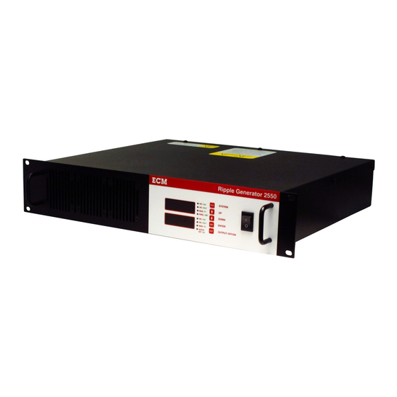
Introduction The Ripple Generator Model 2550 Ripple Generator 2550 is an electronic device capable of superimposing AC voltage waveforms onto the output of a DC supply. This combined AC plus DC waveform can then power a Device Under Test (DUT) to test the DUT for immunity to “noise” on its power supply. - Page 6 Operating: 5 to 40 °C Operating Temperature Storage: 0 to 50°C Humidity 0-95% Relative Humidity. Non-condensing. Altitude Up to 2000m. For de-rating at high altitude contact ECM. Internal fans with front intake and rear exhaust. See section Cooling “Location Mounting” cooling installation requirements.
- Page 7 CANopen Baud Rate 500kHz (default) Galvanic Isolation 200V DC (Ground shared with RS-232) Configuration ECM Configuration Tool via CANopen protocol Line Termination 121 ohm selectable via rear panel switch Term. 2: CAN_L Pinout Term. 3: Ground (DB9 Female on back panel) Term.
- Page 8 Ripple Generator 2550 SYSTEM VAC / kHz 3.39 VIN / VOUT WAVE / P1 PANEL / RMT DOWN VAC / kHz VIN / VOUT ENTER WAVE / P2 OUTPUT OFF/ON OUTPUT OFF / ON 1.33 1.33 19.00 17.54 15.08 1.25 1.08...
-
Page 9: Important Safety Information
Ripple Generator, as well as in end-user equipment can, retain charge which could result in injury if not properly discharged before handling. Engine Control and Monitoring (ECM) and its subsidiary sales organizations take no responsibility for improper use of equipment which results in death, bodily harm, damage, or loss of equipment. -
Page 10: Installation And Hardware Setup
Ripple Generator in a humidity-controlled indoor area. This unit contains no internal user-serviceable components. Service is to be performed only by ECM. The Ripple Generator is a standard 2U, 19” rackmount enclosure. Support for the unit in an equipment rack can be provided by slides along the sides of the rack and four mounting holes on the front panel. -
Page 11: Input Supply And Output Load Connection
Input Supply and Output Load Connection Wiring for the input supply and load connections is made through four ITT Snaplock connectors on the rear panel of the unit, as shown in Figure 4. The input supply to the Ripple Generator can be either a regulated DC source, or a chemical battery. -
Page 12: Connections And Controls
Connections and Controls Ripple Generator 2550 SYSTEM VAC / kHz VIN / VOUT WAVE / P1 PANEL / RMT DOWN VAC / kHz ENTER VIN / VOUT WAVE / P2 OUTPUT OFF/ON OUTPUT OFF / ON NOTES: COOLING FAN AIR INTAKE... -
Page 13: How To Use
How to Use Overview Locations of the front panel controls are shown in Figure 3. Using the front panel rocker switch, turn on the Ripple Generator. The display should become active and run through a power-up sequence. Once fully powered on, the upper and lower displays will show their pre- programmed parameters. -
Page 14: Front Panel Display
In RUN mode, two things other than data can be displayed: “ERR” and “####” where “####” is an error code. See Appendix B. “----“ which means that the unit has an internal problem, consult ECM. When in SYS mode, configuration options for the device will be shown. Pressing the keys will scroll through the setup options, see Table 5. -
Page 15: Sys Setup Options
SYS Setup Options This setting is the AC voltage amplitude of the noise ripple. So if it is set at 10V, then the output will go up 10V and down 10V from the DC input voltage. Valid range is from 0.00V to 50.00V, however the maximum value is limited to one quarter of the input voltage. - Page 16 P2 (on the bottom display). Each parameter is independently configurable in the “P1P2” menu item. The available parameters for P1 and P2 are in Table 6. Table 6: Parameter List for the Ripple Generator 2550 Name Full Parameter Name...
- Page 17 RMOT The Ripple Generator can be controlled by the front panel or by a remote master communicating over either CAN or RS232. Only one can be selected at a time. For control via the front panel, select “OFF” and remote configurations will be disabled. Select “CAN” or “RS23”...
-
Page 18: Can Communication Protocol
NID. For example, communicating with the devices via software on a computer, such as the ECM Configuration Tool. Software on a computer is not a device, therefore, does not need to be assigned a NID. - Page 19 A TPDO message consist of two pieces of data, called Process Data Object (PDO), that is transmitted by the Ripple Generator 2550. Each Ripple Generator can transmit up to four TPDOs at a programmable broadcast rate. The data contained in the TPDO is programmable from a list of available parameters (see Table 6).
- Page 20 SDOs (Service Data Objects) SDO messages are used to read or write to elements in a table of configuration parameters called the Object Dictionary (OD) stored in the Ripple Generator. They consist of two types: received and transmitted. Received SDOs are messages sent from a master to slave device to command a read or write of parameters.
-
Page 21: Controlling Ripple Generator Via Can
Byte 3 Byte 4 Byte 5 Bye 6 Byte 7 0x600 + NID 0x40 0x52 0x50 0x00 The reply from the Ripple Generator 2550: CANid Byte 0 Byte 1 Byte 2 Byte 3 Byte 4 Byte 5 Bye 6 Byte 7... - Page 22 0x01 data 3 data 2 data 1 data 0 Where data0~3 is the 4 byte hexadecimal representation of the floating point step value. The reply from the Ripple Generator 2550: CANid Byte 0 Byte 1 Byte 2 Byte 3 Byte 4...
-
Page 23: Setup User-Defined Waveforms
Byte 4 Byte 5 Bye 6 Byte 7 0x600 + NID 0x2F 0x23 0x10 0x01 OS cmd The reply from the Ripple Generator 2550: CANid Byte 0 Byte 1 Byte 2 Byte 3 Byte 4 Byte 5 Bye 6 Byte 7... -
Page 24: Other Can Configurations
Other CAN Configurations Change Node Id The Node ID (NID) can be programmed from 0x01 to 0x7F (1 to 127). To change the NID, several messages must be sent, followed by a reset of the device. Start by sending the following message to place the module into pre-operational mode. CAN id byte 0 byte 1... - Page 25 Byte 3 Byte 4 Byte 5 Bye 6 Byte 7 0x600 + NID 0x40 0x00 0x18 0x05 The reply from the Ripple Generator 2550: CANid Byte 0 Byte 1 Byte 2 Byte 3 Byte 4 Byte 5 Bye 6 Byte 7...
- Page 26 TPDO Enable/Disable Each TPDO each can be individually enabled or disabled from transmitting. The OD Index of the TPDO enable/disable configurations for each TPDO are located in table below. This OD location also configures the CAN ID from which the TPDOs will be sent. Below lists the default value.
- Page 27 Byte 4 Byte 5 Bye 6 Byte 7 0x600 + NID 0x2F 0x23 0x10 0x01 0xDF The reply from the Ripple Generator 2550: CANid Byte 0 Byte 1 Byte 2 Byte 3 Byte 4 Byte 5 Bye 6 Byte 7...
-
Page 28: Rs232 Communication Protocol
RS232 Communication Protocol NOT IMPLEMENTED... -
Page 29: Appendices
Appendices Appendix A: Entering Decimal Numbers There are times when a decimal number must be entered in the system setup menu. With the limited number of display characters and buttons, this can be tricky. The procedure for entering a decimal number is explained in this section. Each character position can be scrolled up and down to display the following characters: ‘-’... -
Page 30: Appendix B: Error Codes
Appendix B: Error Codes Table B.1: Generic CANopen Error Codes CO ERROR CODE DESCRIPTION OF ERRORS 0x0000 - 00FF No error or error reset 0x1000 - 10FF Generic 0x2000 - 20FF Current 0x2100 - 21FF Current - Device inputs 0x2200 - 22FF Current - Inside the module 0x3000 - 30FF Voltage... - Page 31 Table B.2: ECM Error Codes ECM ERROR CODE DESCRIPTION OF ERRORS 0x0000 All OK 0x0071 IGBT Error 0x0072 Top FET Error 0x0073 Bottom FET Error 0x0074 FET Module Overheated IGBT Overheat 0x0075 0x00A1 Invalid software state 0x00B1 CAN overrun 0x00B2...
-
Page 32: Appendix C: Os Commands
Byte 2 Byte 3 Byte 4 Byte 5 Bye 6 Byte 7 0x580 + NID 0x60 0x23 0x10 0x03 Reply Below is a list of OS commands for the Ripple Generator 2550, along with the OS replies for each, if any. - Page 33 Command Value Description Reply ResetTPDOs 0x1F Set all TPDOs as delivered from None factory. DisableTPDOCOBReset 0x22 Do not allow CAN id's to be set by None CANopen spec. This affects TPDO's 1- 4, Heartbeat, Error messages. EnableTPDOCOBReset 0x23 CAN id's set by CANopen spec based None on module's NID.
-
Page 34: Warranty And Disclaimers
The warranty is void if Ripple Generator is opened or serviced by persons other than ECM qualified technicians. LIMITATION OF REMEDY... - Page 36 Los Altos, CA 94023-0040 • USA • (408) 734-3433 • Fax: (408) 734-3432 • www.ecm-co.com...
Need help?
Do you have a question about the Ripple Generator 2550 and is the answer not in the manual?
Questions and answers