Table of Contents
Advertisement
Advertisement
Chapters
Table of Contents

Related Manuals for Trumpf MARS 2


Summary of Contents for Trumpf MARS 2
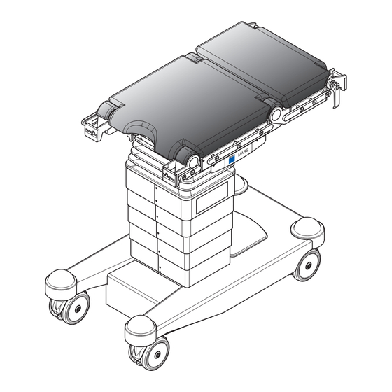
- Page 1 MARS 2 Operating Table Service Manual...
- Page 2 Reprinting, copying or translating this document, in whole or in part, is forbidden without the express written permission of TRUMPF Medizin Systeme GmbH. All rights under the copyright laws are expressly reserved by TRUMPF Medizin Systeme GmbH. Within the bounds of the legal requirements, the manufacturer is only then responsible for the technical safety characteristics of this apparatus if the maintenance, repairs and modifications to this apparatus are performed by him or by someone appointed by him and in accordance with his instructions.
- Page 3 Charging unit IR DVE 230 1 314 349 Charging unit IR DVE 115 1 283 947 Charging unit, panel mounted 1 220 519 for Mars 2.01/2.02 ** for Mars 2.03/2.05 *** for Mars 2.04/2.06 Service Manual MARS 2 1 435 274 - 09/07...
- Page 4 Tabletop height -low- Tabletop with displacement towards the head end (longitudinal displacement) Travel mode can be set mechanically with pedal Travel mode can be set electrically with control unit Electrically driven running gear Service Manual MARS 2 1 435 274 - 09/07...
-
Page 5: Table Of Contents
Toothed belt (main drive) ........48 4.16 Lifting unit limit switches, MARS 2.03 to 2.06 ..... 49 4.17 Trendelenburg limit switch. - Page 6 5.12 Locking unit (not MARS 2.01) ....... . 88 5.13 Distributor board .
- Page 7 Circuit Diagram ........177 Service Manual MARS 2 1 435 274 - 09/07...
- Page 8 Contents Service Manual MARS 2 1 435 274 - 09/07...
-
Page 9: Important Information
Important Information Important Information General information Repairs may only be carried out by TRUMPF service technicians or by persons trained and authorized by TRUMPF. Please follow these instructions exactly, and follow all the specified repair steps. We would be grateful to receive any corrections to the description of the repair or suggestions for improving the efficiency of the repair. -
Page 10: Explanation Of Symbols
NOTE Useful additional information and tips TEST Performance of functional tests, measurements and tests. ENVIRONMENT Notes concerning disposal in ways which do not harm the environment. Service Manual MARS 2 1 435 274 - 09/07... -
Page 11: Liability
• Only use solid rosin flux for brazing work. • Bolts and screws with an M4 or larger thread must be fixated with medium strength screw fixing lacquer (red). Service Manual MARS 2 1 435 274 - 09/07... -
Page 12: Protection Against Infection
• Materials must be disposed of in an environmentally compatible way, and in accordance with the nationally applicable disposal guidelines. • Comply with the recycling obligations for dismounted components, in particular for: - batteries - circuit boards - cables Service Manual MARS 2 1 435 274 - 09/07... -
Page 13: Glossary
Back section joint end (battery compartment) Foot end Leg section joint end (power socket) Right side Side of operating table without membrane keypad Left side Side of operating table with membrane keypad Service Manual MARS 2 1 435 274 - 09/07... -
Page 14: Preparatory Work
- Wooden spacer (for working on lifting motor) - Spirit of wine (degreaser) - Spindle grease (order from TRUMPF Medizin Systeme GmbH) - Wooden spacers 3 mm - Screw clamp (for working on the MARS gas-pressure spring 2.03/2.04/2.05/2.06) Service Manual MARS 2 1 435 274 - 09/07... -
Page 15: Operating Table
CAUTION Risk of tipping over! Brake the operating table. Brake the running gear (MARS 2.01/2.02) or jack up the operating table (MARS 2.03/2.04/2.05/2.06). Do not make any changes to the position of the operating table during repair work unless they are expressly specified. - Page 16 Preparatory work Service Manual MARS 2 1 435 274 - 09/07...
-
Page 17: Emergency Operation
10 seconds. Several short audible signals will be heard until the emergency mode is acknowledged by a long beep. The EMERGENCY OPERATION indicator flashes red continuously. Service Manual MARS 2 1 435 274 - 09/07... - Page 18 Emergency Operation Service Manual MARS 2 1 435 274 - 09/07...
-
Page 19: Repair Guide For The Column
Remove the cover plate [2] (4 countersunk screws [4]), and put them down in a safe place. Remove and safely put down the both battery fuses [5]. Disconnect the positive connectors from the both batteries [3]. Service Manual MARS 2 1 435 274 - 09/07... -
Page 20: Internal Power Supply
Reattach the positive connectors to the both batteries [3]. Insert both battery fuses [5]. Mount the cover plate [2] (4 countersunk screws). Put the battery compartment cover [1] on the running gear. Service Manual MARS 2 1 435 274 - 09/07... -
Page 21: Metal Covers (Without Membrane Keyboard)
6 countersunk screws). Assemble the new metal covers, segment by segment, starting from the inside towards the outside. 10. Guide the remaining cladding components [4] upwards and hook them into place. Service Manual MARS 2 1 435 274 - 09/07... - Page 22 11. Mount the metal cover without membrane keyboard [1] (3 countersunk screws at the upper edge and 4 countersunk screws). 12. Connect the power supply, and switch the operating table on. TEST Check the column functions. Service Manual MARS 2 1 435 274 - 09/07...
-
Page 23: Metal Cover With Membrane Keyboard
10. Make sure that the flat ribbon cable is in its original installation position! Connect the flat ribbon cable MEMBRANE KEYBOARD [5]. 11. Guide the remaining cladding components [4] upwards and hook them into place. Service Manual MARS 2 1 435 274 - 09/07... - Page 24 13. Connect the batteries (see section 4.2 “Internal power supply” page 16). 14. Connect the power supply, and switch the operating table on. TEST Check the column functions using the membrane keyboard. Service Manual MARS 2 1 435 274 - 09/07...
-
Page 25: Head Cover
Place the new head cover [4] carefully on the tabletop. Screw tight the head cover [4] (4 fillister-head screws [5]). 10. Remount the plastic plate [2] on the seat section (4 ball-heads [3]). Service Manual MARS 2 1 435 274 - 09/07... - Page 26 Head cover 11. Press the pad [1] onto the 4 ball-heads [3]. 12. Connect the power supply, and switch the operating table on. TEST Check the column functions. Service Manual MARS 2 1 435 274 - 09/07...
-
Page 27: Expansion Bellows
Note the positions of the cables and the pin configuration! Press the expansion bellows downwards, separate all cable connections to the tabletop and release the tabletop for removal. 10. Unscrew the tilting motor from the tabletop (4 machine screws [10]). Service Manual MARS 2 1 435 274 - 09/07... - Page 28 Lift the tabletop with at least 2 people, and support it during assembly! Lift the tabletop onto the column and install it on the bearing block (tabletop) [11] (8 machine screws [12]). Service Manual MARS 2 1 435 274 - 09/07...
- Page 29 4 countersunk screws). 28. Connect the batteries (see section 4.2 “Internal power supply” page 16). 29. Connect the power supply, and switch the operating table on. TEST Check the column functions. Service Manual MARS 2 1 435 274 - 09/07...
-
Page 30: Connection Unit's Operating Unit, Head End
13. Put the cables back into their original positions, and stick the connection unit’s OPERATING UNIT plug in the corresponding distribution printed circuit board’s [2] socket. Fix the cables with cable binders. Service Manual MARS 2 1 435 274 - 09/07... - Page 31 16. Press the pad onto the 4 ball-heads. 17. Connect the batteries (see section 4.2 “Internal power supply” page 16). 18. Connect the power supply, and switch the operating table on. TEST Check the column functions. Service Manual MARS 2 1 435 274 - 09/07...
-
Page 32: Connection Unit's Operating Unit, Foot End (Not Mars 2.01)
Connection unit’s operating unit, foot end (not MARS 2.01) Connection unit’s operating unit, foot end (not MARS 2.01) IR receiver 2 with RS485/232 Prepare the operating table (see section 2.3 “Operating table” page 11). Raise the column to its highest position. - Page 33 Connection unit’s operating unit, foot end (not MARS 2.01) 14. Put the cables back into their original positions, and stick the connection unit’s OPERATING UNIT plug in the corresponding distribution printed circuit board’s [2] socket. Fix the cables with cable binders.
-
Page 34: Transformer
15. Close the metal cover (2 countersunk screws). 16. Connect the batteries (see section 4.2 “Internal power supply” page 16). 17. Connect the power supply, and switch the operating table on. TEST Check the column functions. Service Manual MARS 2 1 435 274 - 09/07... -
Page 35: Switching Relay
12. Close the metal cover (2 countersunk screws). 13. Connect the batteries (see section 4.2 “Internal power supply” page 16). 14. Connect the power supply, and switch the operating table on. TEST Check the column functions. Service Manual MARS 2 1 435 274 - 09/07... -
Page 36: Membrane Keyboard
13. Connect the batteries (see section 4.2 “Internal power supply” page 16). 14. Connect the power supply, and switch the operating table on. TEST Check the column functions using the membrane keyboard! Service Manual MARS 2 1 435 274 - 09/07... -
Page 37: Electronics
2 machine screws [7]). 12. Put the cables back into their original positions, and connect all cables (see section 9 “Circuit Diagram” page 177). Fix the cables with cable binders. Service Manual MARS 2 1 435 274 - 09/07... - Page 38 17. Transfer the IR code with the PC software. 18. Connect the batteries (see section 4.2 “Internal power supply” page 16). 19. Connect the power supply, and switch the operating table on. TEST Check the column functions. Service Manual MARS 2 1 435 274 - 09/07...
-
Page 39: Motors
Put the wooden spacer [1] in the running gear and lower the column carefully until the lifting column [2] sits on the wooden spacer. Remove the power from the operating table (see section 4.1 “Remove the power from the operating table” page 15). Service Manual MARS 2 1 435 274 - 09/07... - Page 40 19. Connect the power supply, and switch the operating table on. 20. Lift the column slightly with the lifting unit and remove the wooden spacer. 21. Remove retaining screw from the column guide and slide the metal cover downwards. Service Manual MARS 2 1 435 274 - 09/07...
- Page 41 22. Close the metal cover (2 countersunk screws). 23. Mount the cover plate (4 countersunk screws). 24. Put the cover battery compartment on the running gear. TEST Check the column functions. Service Manual MARS 2 1 435 274 - 09/07...
-
Page 42: Trendelenburg Motor
11. Note the positions of the cables. Remove the Trendelenburg motor’s plug from the electronic unit and release the Trendelenburg motor (MARS II Trendelenburg drive) for removal. Service Manual MARS 2 1 435 274 - 09/07... - Page 43 23. Do not jam or damage the expansion bellows. Place the head cover [8] carefully on the tabletop, and screw tight (4 fillister-head screws). 24. Remount the plastic plate [7] on the seat section (4 ball-heads). Service Manual MARS 2 1 435 274 - 09/07...
- Page 44 4 countersunk screws). 30. Connect the batteries (see section 4.2 “Internal power supply” page 16). 31. Connect the power supply, and switch the operating table on. TEST Check the column functions. Service Manual MARS 2 1 435 274 - 09/07...
-
Page 45: Tilting Motor
11. Note the positions of the cables. Remove the tilting motor’s plug from the electronic unit and release the tilting motor (MARS tilting unit - complete) for removal. Service Manual MARS 2 1 435 274 - 09/07... - Page 46 Place the head cover [8] carefully on the tabletop, and screw tight (4 fillister-head screws). 23. Remount the plastic plate [7] on the seat section (4 ball-heads). 24. Press the pad [6] onto the 4 ball-heads. Service Manual MARS 2 1 435 274 - 09/07...
- Page 47 4 countersunk screws). 29. Connect the batteries (see section 4.2 “Internal power supply” page 16). 30. Connect the power supply, and switch the operating table on. TEST Check the column functions. Service Manual MARS 2 1 435 274 - 09/07...
-
Page 48: Spindle
Risk of injury on account of the heavy weight. Turn the operating table with at least 2 people! Turn the operating table on the side without a membrane keyboard and lay down safely on an even surface. Service Manual MARS 2 1 435 274 - 09/07... - Page 49 13. Slightly push the holder [10] into the direction of the column and carefully lift it out from the screws. 14. Carefully pull out the lifting motor from the toothed belt [11]. 15. Put the lifting motor in a safe place. Service Manual MARS 2 1 435 274 - 09/07...
- Page 50 26. Carefully set the lifting motor [9] (lifting unit drive) in the new toothed belt. 27. Make sure that the lifting motor is in its original installation position! Place the lifting motor holder [10] on the screws in the base of the column. Service Manual MARS 2 1 435 274 - 09/07...
- Page 51 4 countersunk screws). 41. Connect the batteries (see section 4.2 “Internal power supply” page 16). 42. Connect the power supply, and switch the operating table on. TEST Check the column functions. Service Manual MARS 2 1 435 274 - 09/07...
-
Page 52: Toothed Belt (Main Drive)
The toothed belt (main drive) is part of the bearing support assembly. If a part of the bearing support is defective, the entire bearing support assembly (with spindle) is always replaced. See section 4.14 “Spindle” page 44. Service Manual MARS 2 1 435 274 - 09/07... -
Page 53: Lifting Unit Limit Switches, Mars 2.03 To 2.06
Unscrew the sensor plate [5] from the guide (3 machine screws, 1 cable clip) and remove carefully. Remove the Hall sensor printed circuit board [6] from the sensor plate [5] (3 machine screws and 1 threaded anchor plate [7]). Service Manual MARS 2 1 435 274 - 09/07... - Page 54 4 countersunk screws). 16. Connect the batteries (see section 4.2 “Internal power supply” page 16). 17. Connect the power supply, and switch the operating table on. TEST Check the column functions. Service Manual MARS 2 1 435 274 - 09/07...
-
Page 55: Trendelenburg Limit Switch
Open the tabletop (see section 4.5 “Head cover” page 21, work steps 5. to 7.). Unscrew the expansion bellows [4] from the tabletop (8 fillister-head screws [6]). Press the bellows [4] carefully down. Service Manual MARS 2 1 435 274 - 09/07... - Page 56 15. Press the pad [1] onto the 4 ball-heads [5]. 16. Connect the batteries (see section 4.2 “Internal power supply” page 16). 17. Connect the power supply, and switch the operating table on. TEST Check the column functions. Service Manual MARS 2 1 435 274 - 09/07...
-
Page 57: Cables
- Slide the metal cover upwards and fix it securely to the column guide with the M6 retaining screw. For cables on the column: - Open the column (see section 4.3 “Metal covers (without membrane keyboard)” page 17, work steps 5. to 7.). Service Manual MARS 2 1 435 274 - 09/07... - Page 58 Do not crush or squeeze the cables! Observe all motion sequences on the operating table. When needed, interrupt the sequence and fix the cable’s position! TEST Check the column functions. 12. Disconnect the power supply cable from the mains supply. Service Manual MARS 2 1 435 274 - 09/07...
- Page 59 19. Mount the cover plate (4 countersunk screws). 20. Put the cover battery compartment on the running gear. 21. Connect the power supply, and switch the operating table on. TEST Check the column functions. Service Manual MARS 2 1 435 274 - 09/07...
-
Page 60: Energy Chain
15. Close the metal cover [1] (2 countersunk screws). 16. Connect the batteries (see section 4.2 “Internal power supply” page 16). 17. Connect the power supply, and switch the operating table on. TEST Check the column functions. Service Manual MARS 2 1 435 274 - 09/07... -
Page 61: Repair Guide For The Tabletop
Unscrew the associated plastic plate [2] (4 ball-heads [3]). Mount a new plastic plate (4 ball-heads [3]). Press the previously removed pad [1] onto the 4 ball-heads [3]. Connect the power supply, and switch the operating table on. Service Manual MARS 2 1 435 274 - 09/07... -
Page 62: Leg Section Gearbox (Ls)
Pull pad [1] off the seat section, and put it down in a safe place. Unscrew the plastic plate [2] (4 ball-heads [3]), and put them down in a safe place. Service Manual MARS 2 1 435 274 - 09/07... - Page 63 15. Remove 6 cylindrical pins [7] with a pin remover, and put them down in a safe place. 16. Remove 6 machine screws [8], and put them down in a safe place. Service Manual MARS 2 1 435 274 - 09/07...
- Page 64 - Tighten the central machine screw [18]. 31. Reattach the positive connectors to the both batteries. 32. Insert both battery fuses. 33. Connect the power supply, and switch the operating table on. Service Manual MARS 2 1 435 274 - 09/07...
- Page 65 42. Mount the cover plate (4 countersunk screws). 43. Put the cover battery compartment on the running gear. 44. Connect the power supply, and switch the operating table on. TEST Check the operating table functions. Service Manual MARS 2 1 435 274 - 09/07...
-
Page 66: Leg Section Motor
12 Leg section toothed belt Pull the self-adhesive covering foil off the seat section strut. Remove the cover (sheet metal guard) [4] (2 machine screws), and put them down in a safe place. Service Manual MARS 2 1 435 274 - 09/07... - Page 67 Check the functional efficiency of the sensor(s) on the corresponding seat section strut. Readjust the sensor(s) if necessary (see section 6 “Adjustment” page 114). 24. Disconnect the power supply cable from the mains supply. Service Manual MARS 2 1 435 274 - 09/07...
- Page 68 31. Mount the cover plate (4 countersunk screws). 32. Put the cover battery compartment on the running gear. 33. Connect the power supply, and switch the operating table on. TEST Check the operating table functions. Service Manual MARS 2 1 435 274 - 09/07...
-
Page 69: Leg Section Toothed Belt
Pull pad [1] off the seat section, and put it down in a safe place. Unscrew the plastic plate [2] from the seat section (4 ball-heads [3]), and put them down in a safe place. Service Manual MARS 2 1 435 274 - 09/07... - Page 70 Remove the toothed-belt cover [9] (4 countersunk screws), and put them down in a safe place. 15. Take note of the mounting position of the toothed belt. Pull the leg section toothed belt [12] through the seat section struts [13], and remove it. Service Manual MARS 2 1 435 274 - 09/07...
- Page 71 Check the functional efficiency of the sensor(s) on the corresponding seat section strut. Readjust the sensor(s) if necessary (see section 6 “Adjustment” page 114). 29. Disconnect the power supply cable from the mains supply. Service Manual MARS 2 1 435 274 - 09/07...
- Page 72 37. Mount the cover plate (4 countersunk screws). 38. Put the cover battery compartment on the running gear. 39. Connect the power supply, and switch the operating table on. TEST Check the operating table functions. Service Manual MARS 2 1 435 274 - 09/07...
-
Page 73: Leg Section Joint (Ls)
Unscrew the standard rail joint [11] (2 countersunk screws), and put them down in a safe place. Remove the self-adhesive covering foils [4] from the left and right of the LS joint [5]. Service Manual MARS 2 1 435 274 - 09/07... - Page 74 18. Remount the plastic plate [2] on the seat section (4 ball-heads [3]). 19. Press the previously removed pad [1] onto the 4 ball-heads [3]. 20. Connect the power supply, and switch the operating table on. TEST Check the operating table functions. Service Manual MARS 2 1 435 274 - 09/07...
-
Page 75: Back Section Gearbox (Bs)
17 Back section toothed belt 11 Cover (sheet metal guard) 18 BS gear Remove the self-adhesive covering foils [5] from the left and right of the strut of the BS joint [8]. Service Manual MARS 2 1 435 274 - 09/07... - Page 76 26. If necessary, attach new self-adhesive covering foils to the left and right of the strut of the BS joint [8]. 27. Connect the red and black cables of the back section motor to the plug (see section 9 “Circuit Diagram” page 177). Service Manual MARS 2 1 435 274 - 09/07...
- Page 77 40. Mount the cover plate (4 countersunk screws). 41. Put the cover battery compartment on the running gear. 42. Connect the power supply, and switch the operating table on. TEST Check the operating table functions. Service Manual MARS 2 1 435 274 - 09/07...
-
Page 78: Back Section Motor
12 Back section toothed belt Pull the self-adhesive covering foil off the seat section strut. Remove the cover (sheet metal guard) [4] (2 machine screws), and put them down in a safe place. Service Manual MARS 2 1 435 274 - 09/07... - Page 79 Check the functional efficiency of the sensor(s) on the corresponding seat section strut. Readjust the sensor(s) if necessary (see section 6 “Adjustment” page 114). 24. Disconnect the power supply cable from the mains supply. Service Manual MARS 2 1 435 274 - 09/07...
- Page 80 31. Mount the cover plate (4 countersunk screws). 32. Put the cover battery compartment on the running gear. 33. Connect the power supply, and switch the operating table on. TEST Check the operating table functions. Service Manual MARS 2 1 435 274 - 09/07...
-
Page 81: Back Section Toothed Belt
13 Back section toothed belt and 17) 14 Seat section strut M5x50 machine screw 15 M3x16 machine screw M8x16 machine screw 16 M4x12 machine screw Back section motor 17 BS gear 10 Toothed-belt cover Service Manual MARS 2 1 435 274 - 09/07... - Page 82 21. Connect the red and black cables of the back section motor to the plug (see section 9 “Circuit Diagram” page 177). 22. Repeat work steps 18. to 21. on the other seat section strut. Service Manual MARS 2 1 435 274 - 09/07...
- Page 83 37. Mount the cover plate (4 countersunk screws). 38. Put the cover battery compartment on the running gear. 39. Connect the power supply, and switch the operating table on. TEST Check the operating table functions. Service Manual MARS 2 1 435 274 - 09/07...
-
Page 84: Back Section (Bs) Joint And Its Components
Carefully knock the tension bolt [1] out with a plastic hammer, and put it down in a safe place. 10. Remove the disc springs [3] and put them down in a safe place. 11. Remove the BS joint [2]. Service Manual MARS 2 1 435 274 - 09/07... - Page 85 The cam lever [7] must move easily. Toothing has no play in tensioned state. If necessary, readjust with shim rings [10]. 18. Connect the power supply, and switch the operating table on. TEST Check the operating table functions. Service Manual MARS 2 1 435 274 - 09/07...
-
Page 86: Back Section Strut
Pull pads [1] off the seat and back sections, and put them down in a safe place. Unscrew the plastic plates [2] from the seat and back sections (4 ball-heads [3] from each), and put them down in a safe place. Service Manual MARS 2 1 435 274 - 09/07... - Page 87 11. Carefully knock the tension bolt [4] out with a plastic hammer, and put it down in a safe place. 12. Remove the disc springs [6] and put them down in a safe place. 13. Remove the BS joint [5], and put it down in a safe place. Service Manual MARS 2 1 435 274 - 09/07...
- Page 88 22. If necessary attach new self-adhesive covering foils [16] to the left and right of the strut of the BS joint [17]. CAUTION Risk of material damage. Ensure that the teeth mesh. The teeth must mesh - not lie tooth on tooth. Attach the BS joint [5]. Service Manual MARS 2 1 435 274 - 09/07...
- Page 89 [3]). 30. Press the previously removed pads [1] onto the 4 ball-heads [3]. 31. Connect the power supply, and switch the operating table on. TEST Check the operating table functions. Service Manual MARS 2 1 435 274 - 09/07...
-
Page 90: Energy Chain (Not Mars 2.01)
Lay the cables into the energy chain (do not cross them over). 10. Hook the energy chain [3] onto the end pieces [4]. Lock the chain links completely together. 11. Fix the cables with cable binders. Service Manual MARS 2 1 435 274 - 09/07... - Page 91 13. Mount the plate (panel) [1] on the side of the seat section strut (2 countersunk screws). 14. Connect the batteries (see section 4.2 “Internal power supply” page 16). 15. Connect the power supply, and switch the operating table on. TEST Check the operating table functions. Service Manual MARS 2 1 435 274 - 09/07...
-
Page 92: Locking Unit (Not Mars 2.01)
Unscrew the plastic plate [2] from the seat section (4 ball-heads [3]), and put them down in a safe place. Figure 49 Locking unit Head cover upper bolt M5x12 machine screw lower bolt Locking unit Service Manual MARS 2 1 435 274 - 09/07... - Page 93 20. Press the seat section pad [1] onto the 4 ball-heads [3]. 21. Connect the batteries (see section 4.2 “Internal power supply” page 16). 22. Connect the power supply, and switch the operating table on. TEST Check the operating table functions. Service Manual MARS 2 1 435 274 - 09/07...
-
Page 94: Distributor Board
Pull pad [1] off the seat section, and put it down in a safe place. Unscrew the plastic plate [2] from the seat section (4 ball-heads [3]), and put them down in a safe place. Service Manual MARS 2 1 435 274 - 09/07... -
Page 95: Distributor Board
11. Place the new distributor board on the snap-in lugs [7] of the holder [6], and click it securely into place. 12. Insert the holder [6] carefully into the tabletop, and mount (4 countersunk screws). Service Manual MARS 2 1 435 274 - 09/07... - Page 96 Seat section strut side Column head side X2 IR/RS485 interface (only MARS 2.01) X7 REF/BP -35° sensors X3 RS485/232 interface (1x MARS 2.01, 2x Mars 2.02-2.06) X9 End sensors X4 HE (head end) IR/interface X13 Spare X5 LE (foot end) IR/interface...
-
Page 97: Longitudinal Displacement (Ld) Microbutton (Not Mars 2.01)
Figure 54 LD microbutton Head cover Distributor board NOTE Do not let any parts fall into the column. Remove the head cover [4] (4 fillister-head screws), and put them down in a safe place. Service Manual MARS 2 1 435 274 - 09/07... - Page 98 18. Remove the holding plate together with LD microbutton and its cable from the column head. 19. Unscrew the defective LD microbutton [9] from the holding plate (2 machine screws). 20. Mount the new LD microbutton [9] on the holding plate (2 machine screws). Service Manual MARS 2 1 435 274 - 09/07...
- Page 99 32. Mount the cover plate (4 countersunk screws). 33. Put the cover battery compartment on the running gear. 34. Connect the power supply, and switch the operating table on. TEST Check the operating table functions. Service Manual MARS 2 1 435 274 - 09/07...
-
Page 100: Or Adapter Sensor Mars 2.01
14. Press the previously removed pads onto the 4 ball-heads. 15. Connect the batteries (see section 4.2 “Internal power supply” page 16). 16. Connect the power supply, and switch the operating table on. TEST Check the operating table functions. Service Manual MARS 2 1 435 274 - 09/07... -
Page 101: Or Adapter Sensor (Not Mars 2.01)
12. Press the seat section pad onto the 4 ball-heads. 13. Connect the batteries (see section 4.2 “Internal power supply” page 16). 14. Connect the power supply, and switch the operating table on. TEST Check the operating table functions. Service Manual MARS 2 1 435 274 - 09/07... -
Page 102: Leg Section (Ls) End Sensor
LS drive unit 11 M3x16 machine screw M5x50 machine screw 12 M4x12 machine screw M8x16 machine screw 13 Leg section toothed belt Leg section motor 14 Terminal block M4x12 countersunk screw Service Manual MARS 2 1 435 274 - 09/07... - Page 103 21. Position the LS end sensor [10] in the seat section strut, and fixate with an countersunk screw [9]. 22. Reattach the positive connectors to the both batteries. 23. Insert both battery fuses. Service Manual MARS 2 1 435 274 - 09/07...
- Page 104 33. Mount the cover plate (4 countersunk screws). 34. Put the cover battery compartment on the running gear. 35. Connect the power supply, and switch the operating table on. TEST Check the operating table functions. Service Manual MARS 2 1 435 274 - 09/07...
-
Page 105: Back Section (Bs) End Sensor
Unscrew the plastic plates [2] from the seat and back sections (4 ball-heads [3] from each), and put them down in a safe place. Pull the self-adhesive covering foils off the right-hand seat section strut. Service Manual MARS 2 1 435 274 - 09/07... - Page 106 14. Pull the defective BS end sensor [10] out of the seat section strut. 15. Push the new BS end sensor [10] through the terminal block [14] in the seat section strut. Service Manual MARS 2 1 435 274 - 09/07...
- Page 107 31. Mount the plastic plates [2] on the seat and back sections (each held by 4 ball- heads [3]). 32. Press the previously removed pads [1] onto the 4 ball-heads [3]. Service Manual MARS 2 1 435 274 - 09/07...
- Page 108 33. Mount the cover plate (4 countersunk screws). 34. Put the cover battery compartment on the running gear. 35. Connect the power supply, and switch the operating table on. TEST Check the operating table functions. Service Manual MARS 2 1 435 274 - 09/07...
-
Page 109: Leg Section Reference Sensor (Ls)
Leg section motor 14 Leg section toothed belt M4x12 countersunk screw 15 Terminal block Remove the cover (sheet metal guard) [4] (2 machine screws), and put them down in a safe place. Service Manual MARS 2 1 435 274 - 09/07... - Page 110 21. Position the LS reference sensor [10] in the seat section strut, and fixate with an countersunk screw [9]. 22. Reattach the positive connectors to the both batteries. 23. Insert both battery fuses. 24. Connect the power supply, and switch the operating table on. Service Manual MARS 2 1 435 274 - 09/07...
- Page 111 Check that the sensors are in good working order. If necessary, readjust the LS reference sensor [10] and the LS -35° sensor [12] (not MARS 2.01) ( see section 6 “Adjustment” page 114). 26. Disconnect the power supply cable from the mains supply.
-
Page 112: Back Section Reference Sensor (Bs)
BS drive unit 11 M3x16 machine screw M5x50 machine screw 12 M4x12 machine screw M8x16 machine screw 13 Back section toothed belt Back section motor 14 Terminal block M4x12 countersunk screw Service Manual MARS 2 1 435 274 - 09/07... - Page 113 - Tighten the central machine screw [12]. 21. Position the BS reference sensor [10] in the seat section strut, and fixate with an countersunk screw [9]. 22. Reattach the positive connectors to the both batteries. Service Manual MARS 2 1 435 274 - 09/07...
- Page 114 33. Mount the cover plate (4 countersunk screws). 34. Put the cover battery compartment on the running gear. 35. Connect the power supply, and switch the operating table on. TEST Check the operating table functions. Service Manual MARS 2 1 435 274 - 09/07...
-
Page 115: Leg Section (Ls) -35° Sensor (Not Mars 2.01)
Leg section motor 14 Leg section toothed belt LS -35° sensor 15 Terminal block Remove the cover (sheet metal guard) [4] (2 machine screws), and put them down in a safe place. Service Manual MARS 2 1 435 274 - 09/07... - Page 116 [12]. 22. Reattach the positive connectors to the both batteries. 23. Insert both battery fuses in the battery compartment. 24. Connect the power supply, and switch the operating table on. Service Manual MARS 2 1 435 274 - 09/07...
- Page 117 33. Mount the cover plate (4 countersunk screws). 34. Put the cover battery compartment on the running gear. 35. Connect the power supply, and switch the operating table on. TEST Check the operating table functions. Service Manual MARS 2 1 435 274 - 09/07...
-
Page 118: Adjustment
PC software service tool under “Actual Trendelenburg value”, and save with the “Calibrate” button (Note: don’t forget the sign of the value input). Return the Trendelenburg to the zero position (Zero position button on remote control/column keypad). Service Manual MARS 2 1 435 274 - 09/07... - Page 119 12. After the calibration, break the connection to the operating table: - “Operating table break connection” - Remove the connecting cable - Switch the operating table Off - Power down the PC/notebook Service Manual MARS 2 1 435 274 - 09/07...
-
Page 120: Leg Section (Ls) End Sensor
• The ends of the leg sections must not have drifted more than 1 cm apart when they reach the final position. • If necessary, readjust the switching distance of the sensor (it must not exceed 0.3 mm). Service Manual MARS 2 1 435 274 - 09/07... -
Page 121: Back Section (Bs) End Sensor
• The ends of the back section struts must not have drifted more than 1 cm apart when they reach the end position. • If necessary, readjust the switching distance of the sensor (it must not exceed 0.3 mm). Service Manual MARS 2 1 435 274 - 09/07... -
Page 122: Leg Section Reference Sensor (Ls)
• The ends of the leg sections must not have drifted more than 1 cm apart when they reach the zero position. • If necessary, readjust the switching distance of the sensor (it must not exceed 0.3 mm). Service Manual MARS 2 1 435 274 - 09/07... -
Page 123: Back Section Reference Sensor (Bs)
• The ends of the back section struts must not have drifted more than 1 cm apart when they reach the zero position. • If necessary, readjust the switching distance of the sensor (it must not exceed 0.3 mm). Service Manual MARS 2 1 435 274 - 09/07... -
Page 124: Leg Section (Ls) -35° Sensor (Not Mars 2.01)
• The ends of the leg sections must not have drifted more than 1 cm apart when they reach the final position. • If necessary, readjust the switching distance of the sensor (it must not exceed 0.3 mm). Service Manual MARS 2 1 435 274 - 09/07... -
Page 125: Repair Guide For The Running Gear
Remove the battery-fastening bracket [5] (2 machine screws) and store safely. Remove the entire battery set. 10. Install a new battery set. 11. Assemble the battery-fastening bracket [5] (2 machine screws). Service Manual MARS 2 1 435 274 - 09/07... - Page 126 15. Put the cover battery compartment [1] on the running gear. 16. Check the charge in the batteries (charge with mains power supply if necessary!). TEST Check the operating table functions. Service Manual MARS 2 1 435 274 - 09/07...
-
Page 127: Mains Socket
Carefully insert the mains socket [4] into the running gear [1] and assemble (2 fillister- head screws [5]). 12. Connect the power supply, and switch the operating table on. TEST Check the operating table functions. Service Manual MARS 2 1 435 274 - 09/07... -
Page 128: Power Supply Fuses
Bear in mind the wiring diagram (page 177) and the fuse overview! Remove the fuses [6] individually; test; and replace if needed. Install fuse socket [5]. Connect the power supply, and switch the operating table on. TEST Check the operating table functions. Service Manual MARS 2 1 435 274 - 09/07... -
Page 129: Battery Fuses
Mount the cover plate [2] (4 countersunk screws [4]). 10. Put the cover battery compartment [1] on the running gear. 11. Connect the power supply, and switch the operating table on. TEST Check the operating table functions. Service Manual MARS 2 1 435 274 - 09/07... -
Page 130: Castor With Locking Device Mars 2.01/2.02
Set the foot lever TRAVEL MODE in the directional travel position (see FOOT LEVER OPERATION pictogram!). Figure 76 Front castor, foot end, with brake and directional travel MARS 2.01/2.02 Front cap Shaft Castor with locking device... - Page 131 17. Set the foot lever TRAVEL MODE in the brake position (see FOOT LEVER OPERATION pictogram!). CAUTION Risk of injuries! Mount the operating table with at least 2 people! 19. Connect the power supply, and switch the operating table on. TEST Check traveling functions! Service Manual MARS 2 1 435 274 - 09/07...
-
Page 132: Castor With Locking Device Mars 2.03/2.05
All LEDs on the membrane keyboard must be out. Remove and safely put down both battery fuses in the battery compartment. Disconnect the positive connectors from the both batteries. Figure 77 Front castor, foot end, with brake and directional travel MARS 2.03/2.05 Front cap Shaft... - Page 133 Mount the operating table with at least 2 people! 25. Mount the cover plate (4 countersunk screws). 26. Put the cover battery compartment on the running gear. 27. Connect the power supply. TEST Check traveling functions! Service Manual MARS 2 1 435 274 - 09/07...
-
Page 134: Front Castor
Unscrew the defective castor [4] (4 machine screws [2]). Note the screw depth of the brake Bowden cable [3]. Unscrew the brake Bowden cable [3] from the axle [5] in the pull frame [6] with the help of pliers. Service Manual MARS 2 1 435 274 - 09/07... - Page 135 CAUTION Risk of injuries! Mount the operating table with at least 2 people! 18. Connect the power supply. 19. only MARS 2.01/2.02 Switch the operating table on. TEST Check traveling functions! Service Manual MARS 2 1 435 274 - 09/07...
-
Page 136: Rear Castor Mars 2.01/2.02
Set the foot lever TRAVEL MODE in the directional travel position (see FOOT LEVER OPERATION pictogram!). Remove the cap from the running gear (behind, on the head end) and store safely. Figure 79 Rear castor at the head end with brake MARS 2.01/2.02 M8x20 machine screw Locking ring 5... - Page 137 17. Set the foot lever TRAVEL MODE in the brake position (see FOOT LEVER OPERATION pictogram!). CAUTION Risk of injuries! Mount the operating table with at least 2 people! 19. Connect the power supply, and switch the operating table on. TEST Check traveling functions! Service Manual MARS 2 1 435 274 - 09/07...
-
Page 138: Rear Castor Mars 2.03 To 2.06
All LEDs on the membrane keyboard must be out. Remove the cap from the running gear (behind, on the head end) and store safely. Figure 80 Rear castor at the head end with brake MARS 2.03 to 2.06 M8x20 machine screw... - Page 139 24. Clip the rear cap on. 25. Jack up the operating table. CAUTION Risk of injuries! Mount the operating table with at least 2 people! 27. Connect the power supply. TEST Check traveling functions! Service Manual MARS 2 1 435 274 - 09/07...
-
Page 140: Brake Bowden Cable
Pull out the brake Bowden cable [3] from the shaft. Make a note of the screw-in depth of the brake Bowden cable [3] at the foot end of the running gear. Service Manual MARS 2 1 435 274 - 09/07... - Page 141 CAUTION Risk of injuries! Mount the operating table with at least 2 people! 17. Connect the power supply. 18. only MARS 2.01/2.02 Switch the operating table on. TEST Check traveling functions! Service Manual MARS 2 1 435 274 - 09/07...
-
Page 142: Directional Travel Bowden Cable Mars 2.01/2.02
[5] of the wheel with locking device [6]. Remove lock washer [7] from the roller [8] and store safely. 10. Remove washer, cable holder [9], and roller [8] from the axle [10] and store safely. Service Manual MARS 2 1 435 274 - 09/07... - Page 143 18. Set the foot lever TRAVEL MODE in the brake position (see FOOT LEVER OPERATION pictogram!). CAUTION Risk of injuries! Mount the operating table with at least 2 people! 20. Connect the power supply, and switch the operating table on. TEST Check traveling functions! Service Manual MARS 2 1 435 274 - 09/07...
-
Page 144: Directional Travel Bowden Cable Mars 2.03/2.05
Unscrew the directional travel Bowden cable [4] out of the cable holder [1] with the help of pliers. 10. At the foot end of the running gear, unhook the directional travel Bowden cable [4] from the lever [5] of the wheel with locking device [6]. Service Manual MARS 2 1 435 274 - 09/07... - Page 145 Mount the operating table with at least 2 people! 26. Mount the cover plate (4 countersunk screws). 27. Put the cover battery compartment on the running gear. 28. Connect the power supply. TEST Check traveling functions! Service Manual MARS 2 1 435 274 - 09/07...
-
Page 146: Directional Travel Bowden Cable Mars 2.04/2.06
Take note of the mounting position of the directional travel Bowden cable! Unscrew the Bowden cable holder [1] from the trip fork [2] (1 machine screw and 1 washer). Note the screw depth of the directional travel Bowden cable [4]. Service Manual MARS 2 1 435 274 - 09/07... - Page 147 24. Put the directional travel Bowden cable back into its original position! At the running gear head end , assemble the Bowden cable holder [1] to the trip fork [2] (1 washer and 1 machine screw). Service Manual MARS 2 1 435 274 - 09/07...
- Page 148 Mount the operating table with at least 2 people! 32. Mount the cover plate (4 countersunk screws). 33. Put the cover battery compartment on the running gear. 34. Connect the power supply. TEST Check traveling functions! Service Manual MARS 2 1 435 274 - 09/07...
-
Page 149: Directional Travel Switch Cable Mars 2.03/2.05
12. Remove cable clip (1 nut) and remove the defective directional travel switch cable [4]. 13. Insert the new directional travel switch cable. Service Manual MARS 2 1 435 274 - 09/07... - Page 150 23. Close the metal cover (2 countersunk screws). 24. Mount the cover plate (4 countersunk screws). 25. Put the cover battery compartment on the running gear. 26. Connect the power supply. TEST Check traveling functions! Service Manual MARS 2 1 435 274 - 09/07...
-
Page 151: Foot Lever Mars 2.01/2.02
Unscrew the counternut [9] and adjusting nut [8] on the head end (drive axle) and store safely. 10. Pull out the directional travel Bowden cable [4] from the locking piece [11] on the foot lever [5]. Service Manual MARS 2 1 435 274 - 09/07... - Page 152 22. Set the foot lever TRAVEL MODE in the brake position (see FOOT LEVER OPERATION pictogram!). CAUTION Risk of injuries! Mount the operating table with at least 2 people! 24. Connect the power supply, and switch the operating table on. TEST Check traveling functions! Service Manual MARS 2 1 435 274 - 09/07...
-
Page 153: Rest Cam Mars 2.01/2.02
Unscrew the counternut [9] and adjusting nut [8] on the head end (drive axle) and store safely. 10. Pull out the directional travel Bowden cable [4] from the locking piece [11] on the foot lever [5]. Service Manual MARS 2 1 435 274 - 09/07... - Page 154 20. Set the foot lever TRAVEL MODE in the brake position (see FOOT LEVER OPERATION pictogram!). CAUTION Risk of injuries! Mount the operating table with at least 2 people! 22. Connect the power supply, and switch the operating table on. TEST Check traveling functions! Service Manual MARS 2 1 435 274 - 09/07...
-
Page 155: Gas-Filled Spring Device Mars 2.01/2.02
11. Assemble retaining rings [1] (4x). 12. Set the foot lever TRAVEL MODE in the brake position (see FOOT LEVER OPERATION pictogram!). CAUTION Risk of injuries! Mount the operating table with at least 2 people! Service Manual MARS 2 1 435 274 - 09/07... - Page 156 Gas-filled spring device MARS 2.01/2.02 14. Connect the power supply, and switch the operating table on. TEST Check traveling functions! Service Manual MARS 2 1 435 274 - 09/07...
-
Page 157: Jacking Up Switch Mars 2.01/2.02
10. Put the cables back into its original positions and secure with cable clip [2] (1 nut [3]). 11. Set the foot lever TRAVEL MODE in the brake position (see FOOT LEVER OPERATION pictogram!). CAUTION Risk of injuries! Mount the operating table with at least 2 people! Service Manual MARS 2 1 435 274 - 09/07... - Page 158 Jacking up switch MARS 2.01/2.02 13. Connect the batteries (see section 4.2 “Internal power supply” page 16). 14. Connect the power supply, and switch the operating table on. TEST Check traveling functions! Service Manual MARS 2 1 435 274 - 09/07...
-
Page 159: Jacking Up Switch Cable Mars 2.01/2.02
10. Insert new jack up switch cable. 11. Put the cables back into their original positions and connect the plug of the new jack up switch cable to the energy chain holder connector assembly. Service Manual MARS 2 1 435 274 - 09/07... - Page 160 18. Close the metal cover (2 countersunk screws). 19. Connect the batteries (see section 4.2 “Internal power supply” page 16). 20. Connect the power supply, and switch the operating table on. TEST Check traveling functions! Service Manual MARS 2 1 435 274 - 09/07...
-
Page 161: Jacking Unit Mars 2.03 To 2.06
Risk of injury from the capacitor voltage. All LEDs on the membrane keyboard must be out. Remove and safely put down both battery fuses in the battery compartment. Disconnect the positive connectors from the both batteries. Service Manual MARS 2 1 435 274 - 09/07... - Page 162 NOTE Pay attention to start-up disks (2 pieces)! Do not allow them to fall into the running gear! Knock out the rear articulated axle [7] downwards and store safely. Service Manual MARS 2 1 435 274 - 09/07...
- Page 163 34. Remove retaining screw from the column guide and slide the metal cover downwards. 35. Close the metal cover (2 countersunk screws). 36. Mount the cover plate (4 countersunk screws). 37. Put the cover battery compartment on the running gear. Service Manual MARS 2 1 435 274 - 09/07...
- Page 164 Jacking unit MARS 2.03 to 2.06 38. Connect the power supply. TEST Check traveling functions! Service Manual MARS 2 1 435 274 - 09/07...
-
Page 165: Hall Sensor Circuit Board Mars 2.03 To 2.06
10. Take note of where the cables have been laid. Remove the Hall sensor printed circuit board plug from the connector assembly on the energy chain holder. Service Manual MARS 2 1 435 274 - 09/07... - Page 166 Hall sensor circuit board MARS 2.03 to 2.06 Figure 93 Hall sensor circuit board MARS 2.03 to 2.06 Jumper ring Hall sensor circuit board M5x16 machine screw Shaft holder Circuit board plate M3x4 machine screw M3x6 machine screw 10 Disc...
- Page 167 27. Close the metal cover (2 countersunk screws). 28. Mount the cover plate (4 countersunk screws). 29. Put the cover battery compartment on the running gear. 30. Connect the power supply. TEST Check traveling functions! Service Manual MARS 2 1 435 274 - 09/07...
-
Page 168: Travelling Drive Mars 2.04/2.06
11. Take note of where the cables have been laid. Remove the drive unit plug from the connector assembly on the energy chain holder; remove cable binder, and release the cable. Service Manual MARS 2 1 435 274 - 09/07... - Page 169 22. Clamp the wooden spacer [11] between the running gear [9] and the drive unit [5]. 23. The directional travel Bowden cable must be taut! Adjust the directional travel Bowden cable [6] on the jacking shaft [8] (1 threaded pin [7]). Service Manual MARS 2 1 435 274 - 09/07...
- Page 170 30. Close the metal cover (2 countersunk screws). 31. Mount the cover plate (4 countersunk screws). 32. Put the cover battery compartment on the running gear. 33. Connect the power supply. TEST Check traveling functions! Service Manual MARS 2 1 435 274 - 09/07...
-
Page 171: Toothed Belt Travelling Drive Mars 2.04/2.06
Toothed belt travelling drive MARS 2.04/2.06 Remove the entire drive unit from the running gear and store safely. See section 7.22 “Travelling drive MARS 2.04/2.06” page 164, work steps 1. to 15. Figure 96 Toothed belt travelling drive MARS 2.04/2.06... -
Page 172: Drive Roller Mars 2.04/2.06
7.24 Drive roller MARS 2.04/2.06 Remove the entire drive unit from the running gear and store safely. See section 7.22 “Travelling drive MARS 2.04/2.06” page 164, work steps 1. to 15. Figure 97 Drive roller MARS 2.04/2.06 Travelling drive motor... - Page 173 15. Assemble the drive unit motor [1] on the rocker [7] (4 machine screws [2]). 16. Assemble the entire drive unit in the running gear and test. See section 7.22 “Travelling drive MARS 2.04/2.06” page 165, work steps 16. to 33. Service Manual MARS 2 1 435 274 - 09/07...
-
Page 174: Travelling Drive Motor Mars 2.04/2.06
Travelling drive motor MARS 2.04/2.06 Remove the entire drive unit from the running gear and store safely. See section 7.22 “Travelling drive MARS 2.04/2.06” page 164, work steps 1. to 15. Figure 98 Travelling drive motor MARS 2.04/2.06 Travelling drive motor... -
Page 175: Gas-Filled Spring Device Mars 2.04/2.06
Gas-filled spring device MARS 2.04/2.06 Remove the entire drive unit from the running gear and store safely. See section 7.22 “Travelling drive MARS 2.04/2.06” page 164, work steps 1. to 15. Figure 99 Gas-filled spring device MARS 2.04/2.06 Jacking shaft... - Page 176 16. Remove and safely put down the screw clamp. 17. Assemble the entire drive unit in the running gear and test. See section 7.22 “Travelling drive MARS 2.04/2.06” page 165, work steps 16. to 33. Service Manual MARS 2 1 435 274 - 09/07...
-
Page 177: Lubrication Plan
Lubrication point Lubricant/insertion additional lubrication Locking device LD: PROFI TURBOGREASE 2 years ⇒ bolt, bearing bush, axles, (mat. no. 4 150 050) spray gear teeth does not apply to MARS 2.01 Service Manual MARS 2 1 435 274 - 09/07... -
Page 178: Column
(mat. no. 1 259 074, with pointed nozzle) CAUTION: Do not lubricate in the lowermost stroke position! Raise the tabletop at least 10 cm! Perform the lubrication on all sides! Service Manual MARS 2 1 435 274 - 09/07... - Page 179 Lubricant/insertion additional lubrication Push tube guide PROFI TURBOGREASE 2 years ⇒ (mat. no. 4 150 050) spray Trendelenburg PROFI TURBOGREASE 2 years ⇒ trapezoidal spindle (mat. no. 4 150 050) spray Service Manual MARS 2 1 435 274 - 09/07...
-
Page 180: Running Gear Mars
TURMOPLEX L220 (mat. no. 4 150 047) 2 years ⇒ apply with brush MARS 2.01 - 2.02 Rest cam TURMOPLEX L220 (mat. no. 4 150 047) 2 years ⇒ apply with brush Service Manual MARS 2 1 435 274 - 09/07... -
Page 181: Circuit Diagram
LV - longitudinal displacement Note: connected to TT.J2.9/10, TB - Trendelenburg The REF LS und END LS sensors in the zero series MARS 2.08 are faulty connected but insulated/unused to TT.DT -MARS 2.07-2.08 FW - running gear due to a mounting error (cam plates reversed). To compensate this were also against... - Page 182 MARS 2 Operating Table Service Manual MARS 2 1 435 274 - 09/07...
- Page 184 TRUMPF Medizin Systeme GmbH Postfach 24 44 D-07310 Saalfeld, Germany Telephone: +49 3671 586-0 e-mail: info@de.trumpf-med.com Telefax: +49 3671 586-166 www.trumpf-med.com...
Need help?
Do you have a question about the MARS 2 and is the answer not in the manual?
Questions and answers