Table of Contents
Advertisement
Advertisement
Table of Contents

Related Manuals for Trumpf TruLight 1000


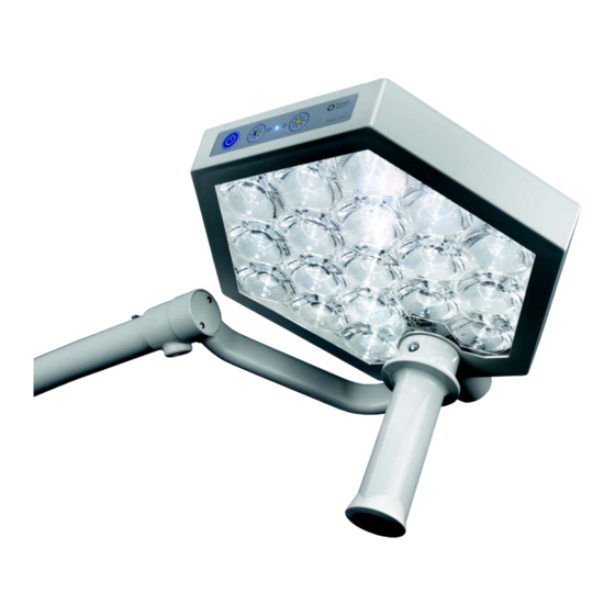
Summary of Contents for Trumpf TruLight 1000
- Page 1 Installation manual TruLight™ 1000 examination light English en-GB...
- Page 2 This page is left intentionally blank.
- Page 3 • Version with light head as ceiling-mounted version. • Version with light head as wall-mounted version. • Version with light head as mobile pedestal version. • Version with a light head on TRUMPF Medizin Systeme GmbH + Co. KG ceiling-mounted supply unit. 55000-00019_002_01 – 1695231 – 17/10/2018...
- Page 4 The contact details for the current sites of the technical customer service in the indi- vidual countries are provided on the Internet at www.trumpfmedical.com. In the following, Technical Customer Service will be used as a synonym for Trumpf Medical Customer Service and for technicians of service operators authorised and trained by Trumpf Medical.
- Page 5 Validity Other applicable documents Designation Document number Material No. Service Manual 55000-00022 1867293 TruLight 1000 DE Spare Parts List 55000-00039 1857652 TruLight 1000 DE / EN Instruction Manual 55000-00012 1695232 TruLight 1000 DE 55000-00019_002_01 – 1695231 – 17/10/2018...
- Page 6 • All rights reserved. This installation manual is protected by copyright. Copyright • Any use not currently regulated by law must be approved in writing by TRUMPF Medizin Systeme GmbH + Co. KG, hereinafter referred to as Trumpf Medical. • Trumpf Medical will assume no liability whatsoever arising from or connected with the use of unapproved information by any person or company.
-
Page 7: Table Of Contents
Table of Content Important information for safe installation ............... 10 Details for identification of the device......................10 Details for identification of the installation manual ..................10 Delivery ................................10 1.3.1 Transportation damage ..............................10 1.3.2 Identifying the components based on serial numbers .......................11 Required installation equipment ........................ - Page 8 Table of Content Connecting the on-site power supply ......................29 5.6.1 Input voltage 100 V - 240 V..............................29 Mount canopy..............................29 Installation of the support arm system on the central axis ................30 5.8.1 Preparing for the assembly..............................30 5.8.2 Dismantling the circlip ................................30 5.8.3 Mounting the circlip................................32 5.8.4...
- Page 9 Table of Content Controlling the driving movements ........................ 60 7.8.1 Rotation / swivel ranges of the spring arm.........................60 7.8.2 Rotation / swivel ranges of the light head ..........................60 Functional testing and instruction ..................61 Functional test of the lighting system......................61 Handover of the lighting system ........................
-
Page 10: Important Information For Safe Installation
(light head or support arm system). 1.3.1 Transportation damage Claims for damage cannot be accepted unless Trumpf Medical is notified without Damage claims delay. In the event of damage during transport or missing components, please send Trumpf Medical a report containing the following information: •... -
Page 11: Identifying The Components Based On Serial Numbers
Trumpf Medical Online Information System (OIS). Qualification of service staff The device may only be installed, maintained and repaired by the Trumpf Medical Professional qualifications Customer Service unit or by authorised Trumpf Medical Service partners. -
Page 12: Conformity
Important information for safe installation Conformity 1.7.1 Identification The manufacturer declares that this product conforms to the fundamental Conformity requirements according to MDD Appendix I and documents the same by means of the CE and UL marking. CE mark: This device is a Class I medical device as defined by the European Medical Device Directive (MDD). -
Page 13: Exclusion Of Liability
Installation must be performed with the use of an installation report (TK_IS_200). Download the specified report in electronic format via the online information system, complete it and hand it over to the Technical Customer Services unit of TRUMPF Medizin Systeme GmbH & Co. KG. -
Page 14: On-Site Requirements
On-site requirements Care must be taken to ensure that the ceiling and wall anchorage of the lighting system takes into account all the circumstances that apply to each individual case, that the approval of the relevant building authorities has been obtained and that all installation work is carried out in accordance with the regulations and using suitable tools. -
Page 15: On-Site Electrical Installation
On-site requirements Load data for wall anchorage: Weight force Bending moment 70 N 70 Nm On-site electrical installation ™ The on-site electrical connections must be made in accordance with the TruLight 1000 planning rules by a specialised company appointed by the customer. The following requirements must be complied with: •... -
Page 16: Safety Instructions
Safety instructions Structure of the safety instructions in this installation manual In this installation manual, important information is marked by graphic symbols or signal words. 3.1.1 Indicating risk of injury Signal words such as DANGER, WARNING or CAUTION indicate the severity of the hazard. -
Page 17: Overview Of The Most Important Safety Instructions
Safety instructions Follow the Instruction Manual: refers to the instruction manual UL mark: device has been tested by Underwriter Laboratories Inc. for the USA and Canada. UL / cUL classification regarding electric shock, fire hazard and mechanical hazard only in accordance with ANSI / AMI ES60601-1: 2005/AMD1: 2012, IEC 60601-2-41:2009/AMD1:2013, CAN/CSA-C22.2 No. - Page 18 Safety instructions Load restriction WARNING Crashing of the lighting system The loading of the support arm system is restricted to the max. load. of 30 Nm. • No additional attachments may be installed on the support arm system, except for the light head. •...
- Page 19 The components of the lighting system are pre-configured and pre- assembled for a system according to the order-specific dimension sheet. • In case of unclear assignment of components, you must consult Trumpf Medical or the appropriate authorised partner of Trumpf Medical. 55000-00019_002_01 – 1695231 – 17/10/2018...
-
Page 20: Identification Of The Lighting System
The main serial number also enables components which do not have a serial number themselves to be identified by Trumpf Medical Customer Service, permitting the correct spare parts to be supplied. • The serial numbers 2 identify the individual components of a device. -
Page 21: Markings On The Mobile Stand Version
Identification of the lighting system Figure 2 4.1.3 Markings on the mobile stand version C: Mobile stand version • The device label 1 with the main serial number on the cover of the wall support. • Serial numbers 2 of the individual components are provided at: –... -
Page 22: Installation Of Ceiling Version
Installation of ceiling version Overview of assemblies for Figure 3 central axis The ceiling version has been disassembled into three assemblies for installation: • Central axis assembly; • Support arm system assembly; • Light unit assembly. 5.1.1 Central axis assembly The central axis can be mounted in three variants. - Page 23 Installation of ceiling version • In this case, the slab ceiling must be absolutely even and horizontal. • The central axis consists of: – Ceiling pipe flange plate 4 with power supply unit – Ceiling conduit 7, – Canopy 8 for encasing the ceiling pipe flange plate. Figure 4 Length of the ceiling pipes The ceiling pipe 7 comes in ready-made sections for the...
-
Page 24: Support Arm System Assembly
Installation of ceiling version Figure 5 5.1.2 Support arm system assembly B: The support arm system is pre-assembled and consists of: – horizontally rotating boom B, – and the horizontally and vertically adjustable spring arm A. 5.1.3 Light unit assembly C: The light unit is partially pre-assembled and consists of: –... -
Page 25: Attachment Of Ceiling Anchor Plate To The Slab Ceiling
Installation of ceiling version Attachment of ceiling anchor plate to the Figure 6 slab ceiling Before starting the installation work: • Check structural evidence about the condition and load- bearing capacity of the fastening substructure. • Check the suitability of the fastening means in accordance with the structural specifications. -
Page 26: Installation Of Ceiling Pipe Flange Plate On The Ceiling Anchor Plate
Installation of ceiling version Installation of ceiling pipe flange plate on Figure 7 the ceiling anchor plate 5.4.1 Installation with threaded rods 45 Nm : Installation of ceiling pipe flange plate 3 of the central axis on the ceiling anchor plate 1 of an intermediate ceiling construction with a slab ceiling / intermediate ceiling gap of ... -
Page 27: Assembly With Hexagonal Profiles
Installation of ceiling version Figure 8 5.4.2 Assembly with hexagonal profiles : Installation of ceiling pipe flange plate 4 of the central axis on the ceiling anchor plate 1 of an intermediate ceiling construction with a slab ceiling / intermediate ceiling gap of >... -
Page 28: Installation Of Ceiling Pipe Flange Plate On The Slab Ceiling
Installation of ceiling version Installation of ceiling pipe flange plate on Figure 9 the slab ceiling Installation of the ceiling pipe flange plate of the central axis directly on the slab ceiling. Before starting the installation > 120 mm work: •... -
Page 29: Connecting The On-Site Power Supply
Installation of ceiling version Connecting the on-site power supply Figure 10 Connect the on-site connecting cables to the terminal block 2 of the ceiling pipe flange plate 1 according to the circuit diagrams attached. 5.6.1 Input voltage 100 V - 240 V •... -
Page 30: Installation Of The Support Arm System On The Central Axis
Installation of ceiling version Installation of the support arm system on Figure 11 the central axis The support arm system has been pre-assembled with: • the horizontally rotating boom 7; • the horizontally and vertically adjustable spring arm 6, • the internally connected cables for the power supply to the light head in the central axis 1 and in both support arms: –... - Page 31 Installation of ceiling version during assembly or disassembly, the circlip will slip out of the groove in the bearing pivot. As a result, the spring arm, adapter and light unit can crash and the internal electrical supply lines can be torn off. This can result in serious injury: •...
-
Page 32: Mounting The Circlip
Installation of ceiling version Figure 13 1. Insert circlip pliers with expansion-limiting means into the eyelets of the circlip 9. 2. Spread circlip 9 carefully so far that it can be just pulled off the protective sleeve. 3. Carefully remove the circlip 9 upward from the protective sleeve. -
Page 33: Checking The Secure Fit Of The Circlip
Installation of ceiling version 5.8.4 Checking the secure fit of the circlip The circlip must lie completely and straight inside the groove provided. This is checked with the following steps: Figure 14 A) Acoustic diagnosis The circlip 1 must audibly snap into the groove on the central axle bearing pin. -
Page 34: Completing The Installation
Installation of ceiling version Figure 17 5.8.5 Completing the installation 1. Check the secure fit of the support arms 5/6 on the central axis 1. 2. Insert the plug 9 into the socket in the bearing pivot. 3. Install the protective cap 4 on the hinge bearing 3 of the boom 6 by inserting the screw 8 through the borehole in the protective cap 4 and into the threaded hole 7 of the hinge bearing 3 into the plug 9. -
Page 35: Installation Of The Light Unit On The Support Arm System
Installation of ceiling version Installation of the light unit on the Figure 18 support arm system The light unit is partially pre-assembled with: • the light head 1 on the quarter bracket 2, • the internally connected cables for the power supply to the light head: –... -
Page 36: Controlling Driving Movements
Installation of ceiling version 6. Adjusting the spring force of the spring arm (see Chapter 9.1, page 65). 7. Check the secure fit of the quarter bracket on the spring arm. 5.10 Controlling driving Figure 19 movements 5.10.1 Check levelling of the lighting system The horizontal movement of the lighting system must be levelled over the entire... -
Page 37: Installation Of Wall Version
Installation of wall version Overview of assemblies of Figure 20 wall bearing The wall version has been disassembled into three assemblies for installation: • Wall bearing assembly; • Support arm system assembly; • Light unit assembly. 6.1.1 Wall bearing assembly A: The wall bearing consists of three components: –... -
Page 38: Power Supply To The Wall Version
Installation of wall version Power supply to the wall version Figure 21 The on-site power supply to the installation site must be installed by the operator. Supply voltage: • The input voltage 100 V - 240 V, 50/60 Hz is transformed into 24 V DC operating voltage on the power supply unit to supply the light head with power. -
Page 39: Fastening The Wall Bearing
Installation of wall version Fastening the wall bearing Figure 22 Before starting the installation work: • Check structural evidence about the condition and load- bearing capacity of the fastening substructure. • Check the suitability of the fastening means in accordance with the structural specifications. - Page 40 Installation of wall version Figure 23 8. Check for secure fit of the wall bearing. The wall bearing must be completely flush to the wall. 9. Place the cover 2 against the wall bearing 5 and firmly press it against the wall bearing so that the clamps engage.
-
Page 41: Connecting The On-Site Power Supply
Installation of wall version Connecting the on-site power supply Figure 24 Power supply with an input voltage of 100 V - 240 V takes place via the power supply box 4, either via: • the fixed connection to connecting cable K, •... - Page 42 Installation of wall version – Guide the on-site connecting cable K through the cable screw connection 7 into the power supply box 4 and secure according to Chapter 6.4 to achieve tension relief. – Connect the on-site connecting cable K to the plug B and the earthing connection 8 according to circuit diagram #1699647.
-
Page 43: Installation Of The Support Arm System On The Wall Bearing
Installation of wall version Installation of the support arm system on Figure 25 the wall bearing The support arm system has been pre-assembled with: • the horizontally rotating boom D, • the horizontally and vertically adjustable spring arm C. • the device-internal, installed cables to supply power to the light head in both support arms: –... - Page 44 Installation of wall version the spring arm, adapter and light unit can crash and the internal electrical supply lines can be torn off. This can result in serious injury: • The circlip must be assembled only by trained technical personnel. •...
-
Page 45: Mounting The Circlip
Installation of wall version Figure 27 C) Dismantling the circlip WARNING Collapse of the support arm system An overstretched circlip may cause the support arm system to collapse: • Open the circlip only so far that it can be precisely guided flat via the pivot pin/ protective cap. -
Page 46: Checking The Secure Fit Of The Circlip
Installation of wall version WARNING Collapse of the support arm system An overstretched circlip may cause the support arm system to collapse: • Carefully spread the circlip only so far that it can be precisely guided over the bearing pivot. •... -
Page 47: Completing The Installation
Installation of wall version Figure 30 C) Mechanical test Place a small, suitable screwdriver on the eyelet 1 of the circlip 2 and turn the circlip 2 carefully in direction of the arrow. • Be careful not to expand the circlip 2 or to squeeze out of the groove. -
Page 48: Installation Of The Light Unit On The Support Arm System
Installation of wall version Installation of the light unit on the Figure 32 support arm system The light unit is partially pre-assembled with: • the light head 1 on the quarter bracket 2, • the internally connected cables for the power supply to the light head: –... -
Page 49: Controlling The Driving Movements
Installation of wall version 6. Adjusting the spring force of the spring arm (see Chapter 9.1). 7. Check the secure fit of the quarter bracket on the spring arm. Controlling the driving Figure 33 movements 6.7.1 Check levelling of the lighting system The horizontal movement of the lighting system must be levelled over the entire... -
Page 50: Assembly Of Mobile Stand Version
Assembly of mobile stand version Overview of assemblies Figure 34 The mobile stand version is supplied for installation in four assemblies: • Stand base assembly; • Stand pipe assembly; • Spring arm assembly; • Light unit assembly. 7.1.1 Stand base assembly A: The stand base consists of the following components: –... -
Page 51: Power Supply Of The Stand Version
Assembly of mobile stand version Power supply of the stand version Figure 35 Power supply is established through the power supply unit 3 by using: • the mains cable with a cold-device plug 5 to connect to the cold-device socket 6 of the power supply unit (on the right side) and a safety plug 4 to connect to a mains socket, •... -
Page 52: Assembling The Stand Base
Assembly of mobile stand version Assembling the stand base Figure 36 Protection against electrostatic charges is achieved by connecting each of the two lockable front castors 3 with standard brake to a pre-installed earth cable 5. The two castors 3 with standard brake must therefore be mounted at the two stand base stabilisers 4 that have an earth cable 5 installed. -
Page 53: Assembling The Stand Rod
Assembly of mobile stand version Assembling the stand rod Figure 37 The stand rod 1 is bolted with a butterfly screw 9 to the stand base 7. The two-section holder plate 5 of the power supply unit 4 is fastened to the stand rod by using the clamping ring D. -
Page 54: Assembly Of The Spring Arm On The Stand Rod
Assembly of mobile stand version Assembly of the spring arm on the stand Figure 38 NOTE Compensating for the gap width The gap B between the hinge bearing support 5 of the stand rod 4 and the hinge bearing 6 on the spring arm 7 is compensated by washers 9. - Page 55 Assembly of mobile stand version WARNING Collapse of the support arm system The spring arm, the quarter bracket and the light unit are held in position at the hinge bearing support by a circlip. If the circlip is overextended or wrongly mounted during the installation or removal, the circlips will slide out of the groove in the stand rod.
-
Page 56: Mounting The Circlip
Assembly of mobile stand version Figure 40 1. Insert circlip pliers with expansion-limiting means into the eyelets of the circlip 9. 2. Spread circlip 9 carefully so far that it can be just pulled off the protective sleeve. 3. Carefully remove the circlip 9 upward from the protective sleeve. -
Page 57: Completing The Installation
Assembly of mobile stand version The circlip must lie completely and straight inside the groove provided. This is checked with the following steps: Figure 41 A) Acoustic diagnosis The circlip 1 must audibly snap into the groove at the hinge bearing pivot of the stand. -
Page 58: Connecting The Internal Power Supply
Assembly of mobile stand version Connecting the internal power supply Figure 44 1. Connect the plug 6 and the socket 4. 2. Store the cable with the plug connection in the bearing pivot. 3. Mount the protective cap 1 to the hinge bearing mount by turning the screw 3 through the hole 2 in the protective cap 1 into the threaded hole 5 of the hinge bearing mount. -
Page 59: Installation Of The Light Unit On The Spring Arm
Assembly of mobile stand version Installation of the light unit on the spring Figure 45 The light unit is partially pre-assembled with: • the light head 1 on the quarter bracket 2, • the internally connected cables for the power supply to the light head: –... -
Page 60: Controlling The Driving Movements
Assembly of mobile stand version 6. Adjusting the spring force of the spring arm (see Chapter 9.1). 7. Check the secure fit of the quarter bracket on the spring arm. Controlling the driving Figure 46 movements 7.8.1 Rotation / swivel ranges of the spring arm The following movements can be performed with the spring arm when there is sufficient... -
Page 61: Functional Testing And Instruction
Functional testing and instruction Functional test of the lighting system Figure 47 For all versions of the lighting system, a function test and a visual inspection should be carried out before handover for general operation. ATTENTION Repeat test After replacement of the light head (e.g. after failure of a light bulb), a measurement is required (according to DIN EN 62353 Repeat inspection and test after repairs to electrical medical devices). -
Page 62: Handover Of The Lighting System
• The operator must be instructed during the handover about the permitted adjustments in accordance with the installation manual. • A copy of the handover protocol must be sent to the Trumpf Medical customer service team. 55000-00019_001_01 – 1695187 – 17/10/2018... -
Page 63: Adjustments
Adjustments Adjusting the spring force on the spring Figure 48 The weight of the light head is compensated by a spring which is installed in the spring arm 1. The spring force must be readjusted if the spring arm with the light head sinks down of its own accord. -
Page 64: Adjusting The Brake Force Of The Quarter Bracket
Adjustments Adjusting the brake force of the quarter Figure 49 bracket If the light head does not remain stable in the vertical rotation position, the braking force for the rotation of the light head must be readjusted on the joint between the spring arm 1 and the quarter bracket 2. -
Page 65: Replacing The Internal Equipment Fuse Of The Mobile Stand Version
Adjustments Replacing the internal equipment fuse of Figure 50 the mobile stand version The two fuse holders 2 for internal fuse protection have been installed in the handle 1: • Fine wire fuse with a medium time lag: M 2.0 A. Replace fuse 1. -
Page 66: Consumables
Consumables Handles and brake screws High-wear part Sterilisable handle for light head; 0337642 Plastic (pack of 3) Brake screw with slot; 4025239 on the quarter bracket (light head brake); M10 × 1 mm with a length of 11 mm (2 units) 55000-00019_002_01 –... -
Page 67: Technical Data
Technical data 11.1 Device data Electrical data Designation Electrical data Power unit supply voltage 100 V - 240 V, 50 / 60 Hz Max. power uptake of whole system 50 VA Nominal frequency 50 / 60 Hz Output current with 24 V secondary voltage <... -
Page 68: Emc Information
1 1 Technical data 11.2 EMC information EMC notes WARNING Operate the device only with the stated accessories. TruLight™1000 may only be operated with the accessories stated in the accompanying documents. Operation with accessories, converters or cables other than those stated in the accompanying documents can lead to increased EMC emissions or reduced interference immunity of the device and with it to improper use. - Page 69 1 1 Technical data Guidelines and manufacturer's declaration - electromagnetic immunity NOTE Avoid environments with electromagnetic fields and interference above the given levels Guidelines and manufacturer's declaration - ELECTROMAGNETIC IMMUNITY TruLight™ 1000 is intended for use in the ELECTROMAGNETIC ENVIRONMENT described below. The customer or user should ensure that the TruLight™...
- Page 70 1 1 Technical data Guidelines and manufacturer's declaration - immunity to electromagnetic interference/portable and mobile radio devices Portable and mobile RF communication devices should be used no closer to any part of the TruLight™ 1000, including cables, than the recommended separation distance calculated from the equation applicable to the frequency of the transmitter. NOTE TruLight™...
- Page 71 1 1 Technical data Immunity level of RF fields from wireless communication device Table: Special frequencies Test Band Service Modulation Max. Distance Immunity Fre- (MHz) power level (V/m) quency (MHz) 380 – 390 TETRA 400 Pulse modulation 18 Hz 430 – 470 GMRS 460 Pulse modulation FM ±5 FRS 460...
- Page 72 1 1 Technical data Controlled RF interference variables Recommended separation distances between portable and mobile RF communication equipment and TruLight™ 1000 TruLight™ 1000 is intended for use in an ELECTROMAGNETIC ENVIRONMENT where the radiated RF interferences are monitored. The customer or user can help to prevent electromagnetic interference by maintaining the minimum distances between the portable and mobile RF telecommunication equipment (transmitters) and TruLight™...
-
Page 73: Attachment
Attachment The attachment provides additional information about the installation of the device. 12.1 Contents of attachment 12.1.1 Circuit diagram for ceiling version 100 V - 240 V / #1699488 • Input voltage 100 V - 240 V, 50/60 Hz, operating voltage 24 V, DC •... -
Page 74: Circuit Plan For Ceiling Version 100 V - 240 V / #1699488
1 2 Attachment 12.1.1 Circuit plan for ceiling version 100 V - 240 V / #1699488 Vollseite 180mmInput voltage 100 V - 240 V, 50/60 Hz, operating voltage 24 V, DC 55000-00019_002_01 – 1695231 – 17/10/2018... - Page 75 1 2 Attachment 12.1.2 Circuit diagram for mobile version 100 V - 240 V cable connection / #1699646 • Input voltage 100 V - 240 V, 50/60 Hz, operating voltage 24 V, DC • Connection with mains cable/cold-device installation plug 55000-00019_002_01 –...
- Page 76 1 2 Attachment 55000-00019_002_01 – 1695231 – 17/10/2018...
- Page 77 1 2 Attachment 12.1.3 Circuit diagram for wall version 100 V - 240 V fixed connection / #1699647 • Input voltage 100 V - 240 V, 50/60 Hz, operating voltage 24 V, DC • Fixed connection 55000-00019_002_01 – 1695231 – 17/10/2018...
- Page 78 1 2 Attachment 12.1.4 Drawing of switch cabinet TL 1000, 230V / #1698267 55000-00019_002_01 – 1695231 – 17/10/2018...
- Page 79 1 2 Attachment 12.1.5 Borehole template for ceiling anchor plate, ceiling pipe flange plate / #1690273 A-A ( 1 : 1) 4 x 90° Ø 175 mm Ø 12 mm Ø 80 mm Brennschnitt / flame cut Gewicht / weight: 1,44 kg Deckenankerplatte TL1000 rund Art-Nr.
- Page 80 1 2 Attachment 12.1.6 Borehole template for wall bearing / #4058120 Oberfläche 53028 Oberfläche nach DIN ISO 1302 nicht vermaßte Kanten mit R gerundet Ra in μm / Reihe 2: 12,5 Werkstoff ID-Nr. entspricht: Komm.-Nr. Index Änderung Datum Name Maße ohne Toleranzangabe nach DIN ISO 2768 mK...
-
Page 81: Borehole Template For Wall Bearing / #4058120
1 2 Attachment 55000-00019_002_01 – 1695231 – 17/10/2018... - Page 82 TRUMPF Medizin Systeme GmbH + Co. KG To order, or for more information, please contact; Carl-Zeiss-Straße 7-9 D-07318 Saalfeld Telefon: +49 (0)3671 586-0 MEDICAL EQUIPMENT SPECIALISTS DocStock Pty Ltd Telefax: +49 (0)3671 586-41105 ABN 48 115 268 203 E-Mail: service@trumpfmedical.com P: (02) 8850 7177 www.trumpfmedical.com...
Need help?
Do you have a question about the TruLight 1000 and is the answer not in the manual?
Questions and answers