
Related Manuals for Perlesmith PSTVMC04


Summary of Contents for Perlesmith PSTVMC04
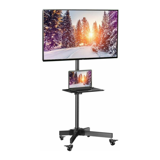
- Page 1 INSTRUCTION MANUAL Rev00(A) PSTVMC04 TV Cart (US/CA) 1-800-556-6806 supportus@perlesmith.com (UK) 44-808-196-3891 www.perlesmith.com WWW.
- Page 2 Before getting started, let's make sure this cart is compatible. Is the VESA pattern Yes - Perfect! of your TV 100 x 100mm (3.9 x 3.9″) to No - This TV cart is NOT 400 x 400mm (15.7 x compatible. 15.7″)? Weight Restrictions TV Plate Maximum Weight...
- Page 3 [Z-B] [Z-A] [Z-D] [Z-A] [Z-A] [Z-B] [Z-C] [Z-A]...
-
Page 4: Supplied Parts And Hardware
Supplied Parts and Hardware TV Bracket Washer Washer Spacer Spacer Spacer M4 / M5 M6 / M8 L2.5mm L10mm L22mm [B1] x 4 [B2] x 4 [F1] x 8 [F2] x 4 [F3] x 4 TV Bolt TV Bolt M4 x 12mm M4 x 30mm [C1] x 4 [C2] x 4... - Page 5 Supplied Parts and Hardware Lower Pole Middle Pole Pole Connector Upper Pole Pole Cover TV Plate Shelf Support Shelf Cable Clip Bolt Washer Bolt Bolt M6 x 10mm M8 x 16mm M4 x 6mm [Z-A] x 11 [Z-B] x 8 [Z-C] x 1 [Z-D] x 4 Allen Key...
- Page 6 Step 1 Attach TV Brackets to TV 1-1 Select TV Bolts Hand thread bolts into the threaded inserts on the back of your TV to determine which bolt (M4, M6 or M8) to use. A minimum of 4-5 turns into the threading is required. Do not turn past the bottom of the hole.
- Page 7 1-3 Attach the TV Brackets to Your TV Round holes should be directed toward the top. Option A: For Flat Back TVs Add spacers if needed to fit the bolt length and TV back. C1/D1/E1 B1/B2 (If needed)
- Page 8 Option B: For Curved TVs Spacers must be tall enough so that the curved back of the TV does not interfere with the mounting plate. C2/D2/E2/E3 B1/B2 F1/F2/F3 Option C: For TVs with a Bump The TV brackets must be flush on the bump and leveled by spacers on the gap. C2/D2/E2/E3 B1/B2 F1/F2/F3...
- Page 9 Option D: For TVs with Protruding Cables Use spacers [F1], [F2] or [F3] to create extra space between the TV and TV brackets. C2/D2/E2/E3 F1/F2/F3 B1/B2 Option E: For TVs with Recessed Holes Spacers [F1], [F2] or [F3] need to fill in the recessed holes on the back of the TV, while keeping the TV brackets as close to the TV as possible.
- Page 10 Step 2 Assemble the Base 5/32″ (4mm) [Z-G] [Z-A] [Z-B]...
- Page 11 Step 3 Secure the Casters [03] to the Base [Z-E] NOTE: Lock the casters to avoid movement during assembly. Unlock Lock Turn the nuts to adjust the mounting height of the casters [03], then screw the casters into the base.
- Page 12 Step 4 Secure the Poles to the Base 5/32″ (4mm) [Z-A] Note the position of [Z-G] screw holes in this step. 3/16″ (5mm) [Z-C] [Z-F] Slide the lower pole [04] into the base, then secure them.
- Page 13 Combine the two parts of each pole connector [06]. 5/32″ (4mm) [Z-G] NOTE: The raised notches on pole connector [06] should be aligned with the round notches on poles. Secure the middle pole [05] and upper pole [07] to the lower pole [04], then attach the pole cover [08].
- Page 14 Step 5 Secure the TV Plate [09] to the Upper Pole [07] The pole has three height options. Choose the best height position for your TV plate before moving on to attach your TV plate to the pole. [Z-H] Clip the level [Z-H] onto the TV plate.
- Page 15 5/32″ (4mm) [Z-B] [Z-A] [Z-G] Secure the TV plate [09] to the upper pole [07]. Make sure the TV plate is leveled. Step 6 Hang the TV on the TV Plate [09] Phillips Screwdriver (NOT lncluded) Slightly loosen preassembled bolts [S] on both brackets.
- Page 16 HEAVY! You may need Phillips Screwdriver assistance with this step. (NOT lncluded) Hang the TV with brackets on the TV plate [09]. Retighten the bolts on brackets to secure TV in place.
- Page 17 Step 7 Secure the Shelf [12] to the Middle Pole [05] Option A: Shelf in the Front Option B: Shelf in the Back Back Front The pole has five height options. Choose the best height position for your shelf before moving on to attach your shelf to the pole.
- Page 18 5/32″ (4mm) [Z-A] [Z-G] Phillips Screwdriver (NOT lncluded) [Z-D] Secure the shelf support [11] to the middle pole [05], then attach the shelf [12].
-
Page 19: Step 8 Cable Management
Step 8 Cable Management [Z-E] Lower Raise NOTE: If the TV cart is not level on the floor, turn the bottom nuts to adjust the caster levels, then tighten the top nuts to fasten. - Page 20 (US/CA) 1-800-556-6806 (UK) 44-808-196-3891 supportus@perlesmith.com WWW. www.perlesmith.com 860-00860-00 Rev00...
Need help?
Do you have a question about the PSTVMC04 and is the answer not in the manual?
Questions and answers