Advertisement
Quick Links
Please Do Not Return This
Product to the Store!
Contact Escalade® Sports customer service department at:
Phone: 1-888-USA-GOAL Toll-Free!
Fax: 1-866-873-3536 Toll-Free!
E-mail: customerservice@escaladesports.com
Escalade® Sports products may be manufactured and/or licensed under the following patents.
6120397, 5816957, 5769744, 5119741, 4911085, 4717157, D460140, D420563, 8414431
Additional patents may be pending. One or more of the listed patents and/or pending patents may cover specific product.
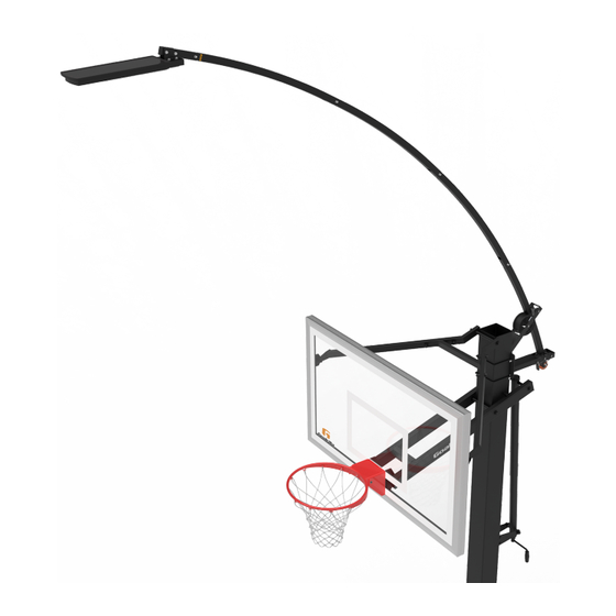
S O L A R - L E D
H O O P L I G H T
MODEL NO.
B2420
2L-
8015
-00
2022 Escalade Sports
Advertisement

Related Manuals for ESCALADE Goalrilla B2420


Summary of Contents for ESCALADE Goalrilla B2420
- Page 1 Fax: 1-866-873-3536 Toll-Free! E-mail: customerservice@escaladesports.com 8015 Escalade® Sports products may be manufactured and/or licensed under the following patents. 6120397, 5816957, 5769744, 5119741, 4911085, 4717157, D460140, D420563, 8414431 2022 Escalade Sports Additional patents may be pending. One or more of the listed patents and/or pending patents may cover specific product.
- Page 2 2-13mm 3/8” drive socket and wrench Pliers Please Do Not Return This Product To The Store! Needle nose pliers 6’ to 8’ Step ladder ® Contact Escalade Sports customer service department at: 1-800-467-1421 Phone: Toll – Free ! E-mail: basketball@escaladesports.com...
- Page 3 SAFETY INSTRUCTIONS FAILURE TO FOLLOW THESE SAFETY INSTRUCTIONS MAY RESULT IN SERIOUS INJURY, PROPERTY DAMAGE AND WILL VOID WARRANTY. Owner must ensure that all players know and follow these rules for safe operation of the system. To ensure safety, do not attempt to assemble this system without following the instructions carefully. Check entire box and inside packing material for parts and/or additional instruction material.
- Page 4 P A R T S L I S T ( N O T A C T U A L S I Z E ) Assemble Together Warning Decal Warning Decal LARGE WHEEL ROLLER BOTTOM BRACKET MOUNTING PLATE ASSEMBLY TOP BRACKET 3M-9044-00 1A-7938-00 8S-7939-00...
- Page 5 L A M P A S S E M B L Y P A R T S L I S T ( N O T A C T U A L S I Z E ) ADJUSTMENT TUBE 120W SOLAR LED HOOPLIGHT 8S-8623-00 ...
- Page 6 H A R D W A R E I D E N T I F I E R ( A C T U A L S I Z E ) *NOTE: DEPENDING ON YOUR MODEL YOU WILL HAVE EXTRA HARDWARE. U-Bolt For 6x8 Pole U-Bolt For 6x6 &...
- Page 7 H A R D W A R E I D E N T I F I E R ( A C T U A L S I Z E ) M8 X 40MM BOLT M8 X 60MM BOLT M8 X 50mm BOLT 1B-7176-00 1B-7265-00 1B-7158-00...
- Page 8 HARDWARE NEEDED (ACTUAL SIZE) HARDWARE NEEDED (ACTUAL SIZE) TOOLS NEEDED 13mm 13mm M8 LOCKNUT M8 LOCKNUT M8X20mm M8X20mm M8 WASHER M8 WASHER 2B-6808-00 2B-6808-00 1B-7156-00 1B-7156-00 2B-6797-00 2B-6797-00 (QTY. 6) 1. Assemble Top Bracket 2 and bottom Bracket 3 together as (QTY.
- Page 9 HARDWARE NEEDED (ACTUAL SIZE) HARDWARE NEEDED (ACTUAL SIZE) 2. Place Large Wheel 4 into the top Bracket 2 and insert 17 as shown. 1/2"X3.5" PIN 7B-6545-00 (QTY. 1)
- Page 10 HARDWARE NEEDED (ACTUAL SIZE) TOOLS NEEDED DETAIL A COTTER PIN 7B-6547-00 Needle Nose (QTY. 1) Pliers 3. Insert Cotter Pin #21 into Pin #17. See Detail A. 4. Bend both prongs on Cotter Pin #21 until pin is secure. See Detail B &...
- Page 11 HARDWARE NEEDED (ACTUAL SIZE) 1/2" X 3.5" PIN 5. Place 3 Small Rollers #5 into the Brackets and 7B-6545-00 (QTY. 3) insert the Pins #17 as shown. SMALL ROLLER 3M-9043-00 (QTY. 3)
- Page 12 HARDWARE NEEDED (ACTUAL SIZE) TOOLS NEEDED DETAIL A COTTER PIN 7B-6547-00 Needle Nose (QTY. 3) Pliers 6. Insert Cotter Pins #21 into Pins #17. See Detail A. 7. Bend both prongs on Cotter Pins #21 until pins are secure. See Detail B & Detail C. DETAIL B Bend DETAIL C...
- Page 13 HARDWARE NEEDED (ACTUAL SIZE) TOOLS NEEDED 13mm 13mm HEX HEAD BOLT M8 X 90mm M8 WASHER M8 LOCKNUT 2B-6808-00 1B-7157-00 2B-6797-00 (QTY. 1) (QTY. 1) (QTY. 2) 8. Insert Height Adjustment Lock #6 into the Bracket #3 and attach with hardware as DETAIL A shown in Detail A.
- Page 14 The Solar LED hoop light can be installed on Goalrilla and Goalsetter basketball systems. Before starting, determine which basketball system you have. Depending on your model the mounting locations will vary. Please refer to your Basketball systems owner’s manual for your Model number.
- Page 15 NOTE: Position the plate as shown. The Mounting location for CV/GS SERIES IMPORTANT studs with the shortest distance to the Models: B3101, B3222, B3333 top side of the plate go at the top. B3100, B3200, B3300 B5000, B5002, B5003 DETAIL A DETAIL A 1.
- Page 16 Mounting location for NOTE: Position the plate as shown. The IMPORTANT studs with the shortest distance to the CV STBLZR SERIES top side of the plate go at the top. Models: B3010, B3011 1. Lower the backboard to the lowest position until the Lower arms touch the safety DETAIL A stop.
- Page 17 NOTE: Position the plate as shown. The Mounting location for DC72E1 IMPORTANT studs with the shortest distance to the Model: B6101 top side of the plate go at the top. NOTE: Make sure your basketball pole is level before mounting the U-bolts #13 and Plate #1.
- Page 18 Mounting location for NOTE: Position the plate as shown. The IMPORTANT studs with the shortest distance to the top side of the plate go at the top. NOTE: Make sure your basketball pole is level before mounting the U-bolts #13 & Plate #1. DETAIL A DETAIL A NOTE: Mounting Plate #1 must be positioned as shown in Detail A &...
- Page 19 TOOLS NEEDED HARDWARE NEEDED 9/16” Deepwell 6’ Ladder Socket BUBBLE LEVEL 2Q-6474-00 9. Center the Mounting Plate 1 on the pole (side to side) and Level it with the provided magnetic (QTY. 1) level 16. Place the level directly on the top studs as shown in Detail A, and adjust until the plate is level (bubble should move to the middle of the level).
- Page 20 HARDWARE NEEDED (ACTUAL SIZE) TOOLS NEEDED NOTE: Having a second person hand you the mounting bracket and hardware is recommended. 13mm 13mm M8 LOCKNUT M8 WASHER 2B-6808-00 2B-6797-00 10. Attach Bracket assembly to the Mounting (QTY. 4) (QTY. 4) plate as shown in Detail A. Tighten Nuts #4 Large Wheel at the top #22 in this step.
- Page 21 HARDWARE NEEDED (ACTUAL SIZE) Mounting location for FT SERIES HARDWARE NEEDED (ACTUAL SIZE) B3015, B3016,B3017 NOTE: Make sure your basketball pole is level before installing the mounting bracket. NOTE: The Goalrilla FT series DO NOT require U-bolts #13, instead the mounting bracket will be attached with hardware #19, #20 &...
- Page 22 HARDWARE NEEDED (ACTUAL SIZE) HARDWARE NEEDED (ACTUAL SIZE) TOOLS NEEDED DETAIL A Solar Panel side up M8 LOCKNUT M8 LOCKNUT M8 X 40MM BOLT M8 WASHER M8 WASHER 13mm 13mm 1B-7176-00 2B-6808-00 2B-6797-00 (QTY. 4) (QTY. 2) (QTY. 8) 12. Attach the Left and the Right Light brackets #29 &...
- Page 23 TOOLS NEEDED 15. Pull back on the Height Adjustment Lock #6 and insert Pole #10B through Small Rollers #5 on the bottom bracket and the Large Wheel Roller #4 on Upper Bracket as shown in Detail A. When in the location shown, let go of the Height Adjustment Lock #6 and the pole will stay in place.
- Page 24 HARDWARE NEEDED (ACTUAL SIZE) TOOLS NEEDED THE FOLLOWING STEPS REQUIRE 2 PEOPLE. 16. IMPORTANT: Before proceeding with the installation, press the GREEN button on the front of M6 WASHER M6 LOCK WASHER M6 X12mm the Solar Light (#7) shown in Detail B below. USE 2B-6827-00 2B-6828-00 1B-7160-00...
- Page 25 HARDWARE NEEDED (ACTUAL SIZE) HARDWARE NEEDED (ACTUAL SIZE) TOOLS NEEDED 19. Insert Center Pole #10A into Top Pole #10B and secure with hardware shown in Detail A & B. 20. Repeat step 20 to install the next three Center Poles #10A and lastly the Bottom Pole #9. 10mm 10mm NOTE:...
- Page 26 DETAIL A 21. Adjust so that the bottom Pole #9 is positioned as shown in Detail A. 22. Insert End Handle #11 shown in Detail B. You may need to tap the End Handle gently with the palm of your hand. DO NOT use a hammer to install the End Handle.
- Page 27 HARDWARE NEEDED (ACTUAL SIZE) HARDWARE NEEDED (ACTUAL SIZE) TOOLS NEEDED 13mm 13mm M8 LOCK NUT WITH CAP M8X50mm BOLT M8 WASHER 2B-6829-00 1B-7158-00 2B-6797-00 (QTY. 1) (QTY. 2) (QTY. 1) 23. Secure End Handle #11 to lower pole with hardware as shown in Detail A.
- Page 28 CAUTION DO NOT LOOK DIRECTLY INTO THE LAMP/LIGHTS! Ÿ NEVER TRY TO OPEN THE LAMP/LIGHT HOUSING AS IT DOES NOT HAVE ANY REPAIRABLE/REPLACEABLE PARTS. OPENING THE Ÿ HOUSING WILL VOID THE WARRANTY DO NOT OPERATE THE SYSTEM WITH ANY BROKEN PIECES OR A DAMAGED LIGHT HOUSING. Ÿ...
- Page 29 3E-6067-00 Remote Control Manual...
- Page 30 Do not try to open, modify, or repair your remote control (except to replace the batteries · periodically as instructed below). This could cause electric shock or injury to you. If your remote control gets wet or it is generally not behaving properly, contact Escalade · Sports Customer Service.
- Page 31 BATTERIES The 3E-6067-00 remote control requires two AAA batteries. The 6Q-6013-00 Solar Powered Light contains a non-serviceable Li-ion battery. Handling disposable batteries This product may contain disposable batteries. Heed the following warning and follow the battery safety and disposal instructions below. WARNING THERE IS DANGER OF EXPLOSION IF THE BATTERY IS MISHANDLED OR INCORRECTLY REPLACED.
- Page 32 First Time Battery Installation: Remote Control ● On the back of the remote control, slide the battery cover in the direction of the arrow to remove it. ● Insert 2 AAA batteries in the correct orientation according to the +/- labels inside the remote control. ●...
- Page 33 WARRANTY DURATION: This Product is warranted to the original consumer purchase of a period of ninety (90) days from the original purchase. WARRANTY COVERAGE: ESCALADE SPORTS warrants to the original Consumer Purchaser that any Product of its manufacture is free from defects in material and workmanship when used for the intended purpose under normal use and conditions.
Need help?
Do you have a question about the Goalrilla B2420 and is the answer not in the manual?
Questions and answers