Advertisement
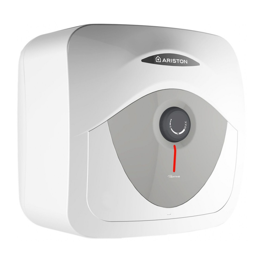
DESCRIPTION OF WATER HEATER

- Hot water outlet (1/2" male BSP)
- Temperature and pressure relief valve (30 litre only)
- Cold water inlet (1/2" male BSP)
- Control cove
- Regulation knob
- Heating neon
TECHNICAL SPECIFICATIONS
For the technical specifications, refer to the nameplate (the nameplate is located next to the water intake/outlet pipes).

(*) 2000W / (**) 3000W
The power consumption data in the table and the other information given in the Product Data Sheet (Enclosure A to this manual) are defined in relation to EU Directives 812/2013 and 814/2013.
Products equipped with regulator knobs have the thermostat positioned in the setting condition at its set <ready to use> position shown in the Data Sheet (Enclosure A), used by the manufacturer to declare the appliance's energy class.
PLEASE KEEP THIS BOOKLET FOR FUTURE REFERENCE
The heater is insulated to a high standard therefore it may be left on all the time. The temperature of the water may be adjusted by turning the knob on the front of the heater, allow half an hour for the temperature to stabilise between settings. Maximum temperature is achieved with the knob turned fully clockwise. The <<E>> mark on the regulation knob indicates an <<economy>> setting and corresponds to a water temperature of 55 - 60°C. In hard water areas we recommended a max. 60°C. The neon light shows when the heating element is working, under control of the thermostat. If in doubt ring Ariston Thermo UK Ltd. Technical department 03332407777 Customer service department 03332408777.
Note: The water heater does not have an "off" or "low" setting.
WATER REGULATIONS AND BYELAWS
These regulations and byelaws ensure a good supply of wholesome water, and that only approved materials, pipes and fittings are used to convey water.
BUILDING REGULATIONS
These are a statutory document and take priority over all other regulations and recommendations. The installation of an unvented hot water system of over 15 litres is classified as a "Controlled Service" and Regulation G3 applies. To meet the requirements of the regulation, installation of an unvented system should be undertaken by a "competent installer".
All installations of unvented hot water storage systems having a capacity of more than 15 litres should be notified to the relevant Local Authority by means of building notice or by the submission of full plans. It is important to note that it is a criminal offence to install an unvented hot water storage system over 15 litres without notifying the Local Authority.
Delivery
The models are supplied with the following:
Unvented water heater (with factory-fitted T&P model 30L) x1
Wall bracket x1
Pressure relief valve set at 6 bar x1
Dielectric junctions x2
Tundish (model 30L only) x1
Expansion Vessel (model 30L only) x1
Check Valve (model 30L only) x1
Pressure reducing Valve (model 30L only) x1

Dielectric junctions must be fitted to all models as they prevent an electrolytic reaction andsafeguard against potential aggressive corrosion.
HOW THE HEATER WORKS
The heating element is controlled by a thermostat which senses the water temperature.
The operating temperature can be adjusted by the regulation knob on the front of the heater. In addition to the thermostat there is a thermal cut-out which is set to switch off the power to the element if the thermostat fails and the water temperature rises too high. Once the cut-out operates it can only be reset manually (this should be carried out by the installer - see maintenance).
A magnesium anode is provided to prevent corrosion of the water container.
The 30L model has a temperature and pressure relief valve on top of the heater which is a safety device to back-up the thermostat and thermal cut-out. It works by sensing an excess water temperature or pressure and releasing the hot water to the discharge tundish and drain.
The heater will only work in the vertical position as the element is shaped to heat the water at the bottom of the tank. The inlet pipe needs to deliver cold water to the bottom of the tank and the hot water outlet draws water from the top of
the tank. When water is heated it expands, in a small unvented water heater of this type the expansion can normally be accommodated back into the cold water mains (not model 30L).
Where this is not possible the installer will need to fit a set of cold water controls.
Note: If a valve i.e. a non return valve, water meter, pressure reducing valve or any type of valve or fitting that acts as a non return valve is installed on the cold water mains, this will prevent expansion. Therefore it will be necessary to install an expansion vessel (see pages 10 figs 2 & 3).
Note: If in doubt always install a pressure reducing valve (limited to 3.5bar) and expansion vessel.
INSTALLATION INSTRUCTIONS
Before installing the heater read these instructions in full. If you are unsure please contact our technical service department (03332407777).
Note: For further information please refer to the flow chart which gives guidance on choosing controls. The installation must comply with all relevant Water Regulations/Byelaws and Building Regulations. The installer should check with the local water authority for confirmation of the maximum water supply pressure.
- SITING & FIXING WARNING:
![]()
The appliance should be left packed until it is ready to be installed. When unpacking the 30 L model take care not to damage the temperature and pressure relief valve on the top of the heater. A drain has to be provided for any water discharged through the safety valves.
Access to the heater is not normally needed on a day-to-day basis, but 300 mm clearance to the front of the water heater sould be kept for servicing and maintenance A cold water supply pressure between 1 and 3.5 bar is required (if the mains pressure is above 3.5 bar a pressure reducing valve must be installed). Please note that turning down the stop-cock will reduce flow not pressure.
The outlet pressure from the reducing valve (if supplied) is 3.5 bar.
A 240 VAC; 3 kW single phase electrical supply is required.
Position the heater against the wall and mark the position of the hooked wall bracket. Fasten the wall bracket to wall using suitable screws and wall plugs (ensure that wall is suitable to support the unit, allowing for the extra weight of water when it is full). Hang the heater on the bracket making sure that the heater is pulled well down on to the bracket, if necessary by forcing the hooks into the foam insulation.
Ensure the unit is accessible and maintains sufficient clearances to allow for service and maintenance. Ensure the unit is installed in a place where freezing will not occur.
Ensure a suitable low level drain off cock is installed on the hot and cold plumbing system. - PLUMBING WARNING:
The appliance must not be supplied with water of hardness less than 120ppm, nor with especially hard water (greater than 250ppm); we recommend installing a water softener, properly calibrated and controlled - do not allow the residual hardness to fall below 150ppm.
The outlet from temperature and pressure relief valve/pressure relief valve must not be for any other purpose. Take great care not to allow any swarf into the pipe work or fittings, as this might impair the operation of the safety valve(s).
The water connection may be carried out as per the following.
Fig. 1 (Note: this system is not suitable for 30L)

- Using the feed pipe to accommodate expansion
(Schedule 2, Section 6: Paragraph 15 of the Water Supply (Water Fittings) Regulations 1999 and the Water Byelaws 2000, Scotland) (Fig. 1).
Do not fit any stop cocks or isolating valves within the distance required for expansion. If a pressure reducing valve is needed, due to a mains pressure of over 3.5 bar, an expansion control kit must be fitted regardless of expansion pipework installed. The expansion distances quoted are for 15mm pipes and can be approximately halved for 22mm pipes. - Using a set of expansion controls (Fig. 2 & 3).
Fig. 2 The tundish must be installed away from electrical devices. (Models 10/15L)
 Fig. 3 (Models 30L)
The model 30L is covered under part G3 of the Building Regulations and therefore it is not permissible to accommodate the expansion water within the system pipe work and consequently a set of expansion controls must be installed.
Note: The discharge pipework from both relief valves must be made so that an fault is visible to the end user therefore a tundish (Kit C) is required for the 30L unit and is recommended for 10 and 15 litre units Please note that in all cases the dielectric junctions must be connected to the heater before any other connection is made (these prevent an electrolytic reaction).
Only the use of copper pipe is recommended for connection to the heater. If any other material is used it must be able to withstand 90°C at 7 bar pressure for long periods.
No valves must be fitted between the expansion and pressure relief valves at any point along any of the safety relief pipework.
All other required safety components to install the model 30L are supplied as a kit with the appliance: 15mm pressure reducing valve set at 3.5 bar. Expansion vessel (charge pressure set at 3.5bar).
- Using the feed pipe to accommodate expansion
- DISCHARGE PIPE WORK NOTE:
The following refers to Building Regulations G3. It is mandatory to follow these rules for all relief valve discharge pipe work.- The tundish should be vertical, located in the same space as the unvented hot water storage system and be fitted as close as possible to, and lower than, the safety device, with no more than 600mm of pipe between the valve outlet and the tundish
- Discharge pipes from the temperature & pressure relief and pressure relief valve may be joined together. The pressure reducing valve should be installed between the nearest draw off and the non-return valve.
- The pipe diameter of the D2 pipework must be at least one pipe size larger than the nominal outlet size of the safety device unless it's total equivalent hydraulic resistance exceeds that of a straight pipe 9 m long. i.e. Discharge pipes between 9 m and 18 m equivalent resistance length should be at least 2 sizes larger than the nominal outlet size of the safety device. Between 18 m and 27 m at least 3 times larger, and so on. Bends must be taken into account in calculating the flow resistance. See fig. 5 and Table 2.
- The D2 pipe work from the tundish should have a vertical section of pipe at least 300mm long below the tundish before any elbows or bends in the pipework and should be at least one size larger than the pipe coming in.
- The discharge pipe must be installed with a continuous fall.
- The discharge must be visible at both the tundish and the final point of discharge, but where this is not possible or practically difficult; there should be clear visibility at one or other of these locations.
Examples of acceptance are:- Ideally below a fixed grating and above the water seal in a trapped gully.
- Downward discharges at a low level; i.e. up to 100 mm above external surfaces such as car parks, hard standings, grassed areas etc. These are acceptable providing that where children may play or otherwise come into contact with discharges, a wire cage or similar guard is positioned to prevent contact, whilst maintaining visibility.
Fig. 4 Suggest ways of terminating discharge pipes safety
![]()
- Discharges at high level; i.e. into a metal hopper and metal down pipe with the end of the discharge pipe clearly visible (tundish visible or not).
Or onto a roof capable of withstanding high temperature discharges of water 3 m from any plastic guttering systems that would collect such a discharge (tundish visible). - Where a single pipe serves a number of discharges, such as in blocks of flats, the num-ber served should be limited to not more than 6 systems so that any installation can be traced reasonably easily. The single common discharge pipe should be at least one pipe size large than the largest individual discharge pipe to be connected. If unvented hot water storage systems are installed where discharges from safety devices may not be apparent i.e. in dwellings occupied by the blind, infirm or disabled people, consideration should be given to the installation of an electronically operated device to warn when discharge takes place. Note: The discharge will consist of scalding water and steam. Asphalt, roofing felt and non-metallic rainwater goods may be damaged by such discharges.

 Fig. 3 (Models 30L)
Table 2 Sizing of copper discharge pipe "D2" for common temperature valve outlets.
| Valve outlet size | Minimum size of discharge pipe D1* | Minimum size of discharge pipe D2* from tundish | Maximum resistance allowed, expressed as a length of pipe (i.e. no elbow or bends) | Resistance created by each elbow or bend |
| G 1/2 | 15 mm | 22 mm 28 mm 35 mm | Up to 9 m Up to 18 m Up to 27 m | 0.8 m 1.0 m 1.4 m |
| G 3/4 | 22 mm | 28 mm 35 mm 42 mm | Up to 9 m Up to 18 m Up to 27 m | 1.0 m 1.4 m 1.7 m |
| G 1 | 28 mm | 35 mm 42 mm 54 mm | Up to 9 m Up to 18 m Up to 27 m | 1.4 m 1.7 m 2.3 m |
WORKED EXAMPLE
tundishThe example below is for a G 1/2" temperature & pressure relief valve with a discharge pipe (D2) having 4 no. elbows and length of 7 m from the tundish to the point of discharge.
From Table 2
Maximum resistance allowed for a straight length of 22 mm copper discharge pipe (D2) from G 1/2" T & P valve is 9 m.
Subtract the resistance for 4 no. 22 mm elbows at 0.8 m each = 3.2 m.
Therefore the maximum permitted length equates to: 5.8 m.
As 5.8 m is less than the actual length of 7 m therefore calculate the next largest size.
Maximum resistance allowed for a straight length of 28 mm pipe (D2) from G 1/2" T & P valve equates to: 18 m.
Subtract the resistance for 4 no. 28 mm elbow at 1.0 m each = 4 m.
Therefore the maximum permitted length equates to: 14 m
As the actual length is 7 m, a 28 mm (D2) copper pipe will be satisfactory.
- ELECTRICAL WARNING:
The appliance must be earthed
The electrical installation must be in line with the current IEE wiring regulations.
A mains supply of 240 VAC 3 kW.
Heat resisting cable, round 3 core 1.5 mm (to BS 6141 table 8) should be used to connect to the electrical supply through 20 amp double pole switch (conforming to BS EN 60669-1).
The appliance must have a dedicated incoming supply that must be protected by an industry standard MCB compliant with the current IEE wiring regulations.
The cable enters the terminal compartment through a tube embedded in the foam insulation, the entrance to this tube is on the rear right hand side at the bottom. Flexible cables are colour coded as follows:
Brown: live
Blue: neutral
Green and yellow: earth
Fig. 5 Wiring Diagram

To enter into the terminal compartment unscrew the 2 screws on the cover.
(To access the screws, remove the decorative caps on the front control access panel.
- COMMISSIONING
- Check that all the necessary components are supplied and for those not factory fitted, that they are the type recommended by the manufacturer for the particular water heater.
- Check that the water heater/components are undamaged.
- Check that the discharge pipe is plumbed so that it falls continuously and that no taps, valves or other shut-off devices are installed in the pipe.
- Check that the discharge pipe drains safely to waste and is readily visible.
- Check, in the case where some components are not factory fitted, that they are marked so as to refer to the warn-ing label on the water heater.
- Open all outlet taps.
- Turn on the mains water supply.
- Close taps in turn as water flow stabilises with no air bubbles.
- Check for leaks.
- Check that no water is passing through the safety valve(s).
- Test the operation of the safety valve(s) by lifting/turning the lever/knob, and observing that water flows through and safely to waste.
- Switch on electricity and set thermostat to at 60°C to reduce the build up of scale in hard water areas.
- Check the water heats up.
- Check that <<warning to user label>> is secure and visible on the heater and related warning labels are fitted to the controls.
- Demonstrate operation to user, including operation of safety valve(s) and what to do if it/they operate(s).
- Give this handbook to the user and discuss future maintenance.
- Drain and refill the entire system ensuring it is flushed in accordance with BS67
INSTALLATION INSTRUCTIONS
- For the user
In order to obtain the best performance from the heater, the sacrificial anode must be checked every year and replaced as necessary. If the heating element is heavily coated with scale we recommend descaling and removing any lime deposit from the heater at the time of this inspection. Where the additional cold water controls are fitted, the expansion vessel will need to be recharged by the installer.
![]()
The heater must be serviced annually. Failure to service which includes inspection and replacement of the sacrificial anode will invalidate warranty. - For the installer
![]()
Switch off the power first.
Access to the electrical components, the magnesium anode and water container is gained by unscrewing the 2 screws on the front cover.
If the thermal cut-out has operated the cause must be found before resetting.
To drain the heater close the service valve and:- for under-sink models disconnect pipes and removed the heater from the wall.
- for over-sink models undo the cold water supply pipe and open a hot water tap.
The heating element may be removed (after taking out the thermostat phials on model 30 L) by undoing the M6 nut.
The assembly should then be turned through 90° anti-clockwise to ease removal from the water container. Once the element is free from the water container the anode may then be inspected and removed if necessary
When reassembling the cover make sure that the regulation knob is coupled with the thermostat.
Check controls (where fitted) as per the following:
- Line strainer - with the water supply turned off remove screen from strainer and clean of any detritus;
- Expansion vessel - with the water supply turned off and taps open, check expansion vessel pressure and top up as necessary;
- Temperature & pressure relief valve - with the water supply turned on, check manually by lifting the test lever/ turning the test knob (ensure valve closes after testing);
- Expansion relief valve - check manually by turning the test knob (ensure valve closes after testing);
- Discharge pipes (D1) - from both temperature & pressure relief and expansion relief valve for obstructions;
- Tundish & discharge pipe (D2)- open either valve gradually to produce a full bore discharge into tundish and D2 without any back pressure;
- Pressure reducing valve - check that the correct outlet pressure is being maintained by recording the pressure at an in-line terminal fitting i.e. tap
FAULT FINDING
Pressure and temperature valve dripping/running all the time
Cause: Thermal cut-out and thermostat have failed (this is only the case if the water being discharged is near to boiling).
Mains pressure is too high. A pressure reducing valve must be fitted (see fig. 3).
Pressure relief valve dripping/running all the time
Cause: Mains pressure is above 3.5 bar.
A pressure reducing valve must be fitted (see fig. 2).
Dripping while unit heating.
Cause: Not enough pipe work for expansion; or stop-cock, non-return valve or pressure reducing valve has been fitted on the cold mains supply (see fig. 2). If an expansion vessel has been fitted, the charge may have failed.
No hot water
Cause: Thermal cut-out has operated.
The heating element has burnt-out.
The thermostat is faulty.
Milky water
Cause:This is a result of heavily limed and oxygenated water being heated. This is harmless and the cause is the water or a loose jumper washer in the outlet tap and not the heater itself.
No water at all
Cause: Valve incorrectly fitted.
Debris in the mains.
Mains water supply turned off.
Grey metallic deposit in the water
Cause: Corrosion of the sacrificial anode.
(Note: Corrosion of the sacrificial anode is normal operation of the unit)
Rapid depletion of the sacrifical anode
Cause: Di-electric junctions not fitted
Water softener fitted on incoming supply to water heater
(Softened will cause the anode to deplete more rapidly than hard water)
Note Whilst Ariston do not advise against the use of water softener devices, the end user must be advised that rapid depletion of the sacrificial anode may occur as a result of the softened water which can result in metallic grey deposit in the water.
10 and 15 litre capacity units can be installed in a number of ways. The following guidelines are designed to help select the correct method prior to installation


GENERAL SAFETY INSTRUCTIONS
- Read the instructions and warning in this manual carefully, they contain important information regarding safe installation, use and maintenance.
This manual is an integral part of the product. Hand it on to the next user/owner in case of change of property. - The manufacturer shall not liable for any injury to people, animals or damage to property caused by improper, incorrect or unreasonable use or failure to follow the instructions reported in this publication.
- Installation and maintenance must be performed by professionally qualified personnel as specified in the relative paragraphs.
Only use original spare parts. Failure to observe the above instructions can compromise the safety of the appliance and relieves the manufacturer of any liability for the consequences. - DO NOT leave the packaging materials (staples, plastic bags, expanded polystyrene, etc.) within the reach of children they can cause serious injury.
- The appliance may not be used by persons under 8 years of age, with reduced physical, sensory or mental capacity, or lacking the requisite experience and familiarity, unless under supervision or following instruction in the safe use of the appliance and the hazards attendant on such use. DO NOT permit children to play with the appliance. User cleaning and maintenance may not be done by unsupervised children.
- DO NOT touch the appliance when barefoot or if any part of your body is wet.
- Before using the device and after routine or extraordinary maintenance, we recommend filling the appliance's tank with water and draining it completely to remove any residual impurities.
- If the appliance is equipped with a power cord, the latter may only be replaced by an authorised service centre or professional technician.
- It is mandatory to screw o the water inlet pipe of the unit a safety valve in accordance with national regulations. In countries which have enacted EN 1487, the safety group must be calibrated to a maximum pressure of 1487 MPa (0,7 bar) and include at least a cock, check valve and control, safety valve and hydraulic load cutout.
- Do not tamper with the overpressure safety device (valve or safety group), if supplied together with the appliance; trip it from time to time to ensure that it is not jammed and to remove any scale deposits.
- It is normal water drips from the overpressure safety device when the appliance is heating. For this reason, the drain must be connected, always left open to the atmosphere, with a drainage pipe installed in a continuous downward slope and in a place free of ice.
- Make sure you drain the appliance and disconnect it from the power grid when it is out of service in an area subject to subzero temperatures.
- Water heated to over 50°C can cause immediate serious burns if delivered directly to the taps. Children, disabled persons and the aged are particularly at risk. We recommend installing a thermostatic mixer valve on the water delivery line, marked with a red collar.
- Do not leave flammable materials in contact with or in the vicinity of the appliance.
- Do not place anything under the water heater which may be damaged by a leak.

LEGIONELLA BACTERIA FUNCTION
Legionella are small rod shaped bacteria which are a natural constituent of all fresh waters. Legionaries' disease is a pneumonia infection caused by inhaling of Legionella species. Long periods of water stagnation should be avoided; it means the water heater should be used or flushed at least weekly.
The European standard CEN/TR 16355 gives recommendations for good practice concerning the prevention of Legionella growth in drinking water installations but existing national regulations remain in force.
This electro-mechanical storage water heater is sold with a thermostat set at a temperature higher than 60°C; it means it is enabled to carry out a "thermal disinfection cycle" to restrict the Legionella growth inside the tank.

water temperature in the tank can cause severe burns instantly. Children, disabled and elderly are at highest risk of being scalded. Feel water before bathing or showering.
![]() Basildon SS15 6SJ
Basildon SS15 6SJ
www.ariston.co.uk
e-mail: info.uk@ariston.com
Customer Service: 0333 240 8777
Technical Advice: 0333 240 7777
Documents / ResourcesDownload manual
Here you can download full pdf version of manual, it may contain additional safety instructions, warranty information, FCC rules, etc.
Advertisement


Need help?
Do you have a question about the Andris R10 and is the answer not in the manual?
Questions and answers