Table of Contents
Advertisement
Quick Links
R32
R410A
EEV internal model
AS*A004HCAH
AS*A005HCAH
AS*A007HCAH
AS*A009HCAH
AS*A012HCAH
AS*A014HCAH
EEV external model
AS*E004HCAH
AS*E005HCAH
AS*E007HCAH
AS*E009HCAH
AS*E012HCAH
AS*E014HCAH
R32/R410A
R32 or R410A.
Refer to the rating label for the serial number, manufactured
year and month.
INSTALLATION MANUAL
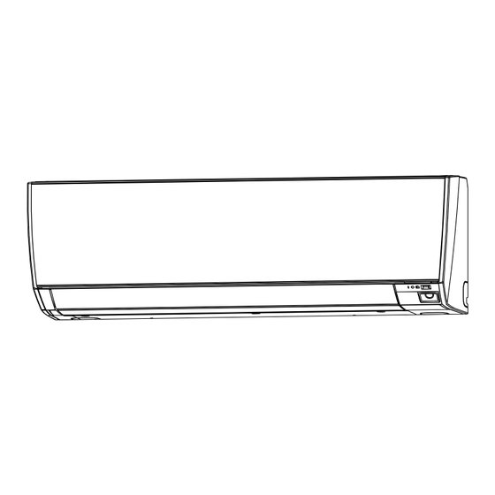
VRF system indoor unit (Wall mounted type)
For authorized service personnel only.
INSTALLATIONSANLEITUNG
VRF-System Innengerät (wandmontierter Typ)
Nur für autorisiertes Fachpersonal.
MANUEL D'INSTALLATION
Unité intérieure à système VRF (Type montage mural)
Pour le personnel agréé uniquement.
MANUAL DE INSTALACIÓN
Unidad interior del sistema VRF (Tipo montado en pared)
Únicamente para personal de servicio autorizado.
MANUALE DI INSTALLAZIONE
Unità interna del sistema VRF (tipo montato a parete)
A uso esclusivo del personale tecnico autorizzato.
ΕΓΧΕΙΡΙΔΙΟ ΕΓΚΑΤΑΣΤΑΣΗΣ
Εσωτερική μονάδα συστήματος VRF (Επιτοιχιος Τύπος)
Μόνο για εξουσιοδοτημένο τεχνικό προσωπικό.
MANUAL DE INSTALAÇÃO
Unidade interior do sistema VRF (Tipo mural)
Apenas para técnicos autorizados.
MONTAJ KILAVUZU
VRF sistemi iç ünitesi (Duvara Monteli Tip)
Yalnızca yetkili servis personeli için.
PART No. 9373370536-01
MADE IN P.R.C.
Advertisement
Table of Contents

Subscribe to Our Youtube Channel
Related Manuals for Fujitsu AS A004HCAH Series


Summary of Contents for Fujitsu AS A004HCAH Series
- Page 1 INSTALLATION MANUAL VRF system indoor unit (Wall mounted type) For authorized service personnel only. INSTALLATIONSANLEITUNG VRF-System Innengerät (wandmontierter Typ) R410A Nur für autorisiertes Fachpersonal. EEV internal model MANUEL D’INSTALLATION AS*A004HCAH Unité intérieure à système VRF (Type montage mural) AS*A005HCAH Pour le personnel agréé uniquement. AS*A007HCAH MANUAL DE INSTALACIÓN AS*A009HCAH...
-
Page 2: Table Of Contents
INSTALLATION MANUAL [Original instructions] CAUTION PART No. 9373370536-01 VRF system indoor unit (Wall mounted type) Read carefully all security information before use or install the air conditioner. Do not attempt to install the air conditioner or a part of the air conditioner by yourself. This unit must be installed by qualified personnel with a capacity certificate for handling Contents refrigerant fluids. - Page 3 CAUTION CAUTION 1. General 3. Repairs to sealed components 1-1 Installation • During repairs to sealed components, all electrical supplies shall be disconnected from • That the installation of pipe-work shall be kept to a minimum. the equipment being worked upon prior to any removal of sealed covers, etc. •...
-
Page 4: About This Product
2. ABOUT THIS PRODUCT CAUTION 10. Decommissioning 2.1. Installation tools • Before carrying out this procedure, it is essential that the technician is completely familiar with the equipment and all its detail. • It is recommended good practice that all refrigerants are recovered safely. WARNING •... -
Page 5: Optional Parts
Detection range of the occupancy sensor 2.3. Optional parts CAUTION Description Model Application Do not hit or push the occupancy sensor. This may lead to damage or malfunction. UTR-EV09XC For AS*E004/005/007/009 Do not touch the occupancy sensor. Any scratches or dirt may lead to incorrect detec- EV kit UTR-EV14XC For AS*E012/014... - Page 6 (1) Fasten the wall hook [For (D) Left bottom piping, (E) Left piping and (F) Left rear piping] Wall hook bracket bracket to the wall with 5 or more screws and CAUTION anchor bolts through Insert the drain hose and drain cap into the drain port, making sure that it comes in con- the holes near the outer tact with the back of the drain port, and then mount it.
-
Page 7: Pipe Installation
Check if [L] is flared uniformly 4. PIPE INSTALLATION and is not cracked or scratched. CAUTION Be more careful that foreign matter (oil, water, etc.) does not enter the piping than with refrigerant R32/R410A models. Also, when storing the piping, securely seal the open- Pipe ings by pinching, taping, etc. -
Page 8: Electrical Wiring
A. Current breaker requirements 5. ELECTRICAL WIRING • MCA: Minimum Circuit Ampacity Model • MFA: Maximum Fuse Ampacity AS*A004HCAH 0.15 A WARNING When the power crossover wiring is done, make it AS*A005HCAH 0.15 A so that the total of the MCA of the connected RB Electrical work must be performed in accordance with this manual by a person certified units and indoor units does not exceed the 15 A. -
Page 9: Unit Wiring
5.3. Unit wiring PROHIBITED GOOD • Before attaching the cable to terminal block. 5.3.1 Power supply cable 20 mm Different diameter Connect to 1 side Earth 40 mm (ground) cable WARNING A. For solid core wiring Tighten the terminal screws to the specified torques, otherwise, abnormal overheating (1) To connect the electrical terminal, follow the below diagram and connect after looping may be occurred and possibly cause serious damage inside the unit. -
Page 10: Optional Parts Wiring
Cover Controller PCB 5.5. Optional parts wiring In this setting, you need to remove the front panel. Refer to “8. FRONT PANEL REMOVAL AND INSTALLATION”. 5.5.1. Layout of the indoor unit PCB CAUTION Do not operate any switches other than prescribed, as it can cause the unit to operate Hooks improperly or malfunction. -
Page 11: Remote Sensor (Optional Parts)
5.6.2. External output 5.7. Remote sensor (Optional parts) • A twisted pair cable (22AWG) should be used. Maximum length of cable is 25 m (82 ft). Connection method • Use an external input and output cable with appropriate external dimension, depending on the number of cables to be installed. -
Page 12: Custom Code Setting
6.1.2 Refrigerant system address Function details • Rotary switch (REF AD × 1)..Factory setting “0” Setting Function Function number Details • Rotary switch (REF AD × 10)..Factory setting “0” number (♦: Default) In the case of multiple refrigerant systems, set REF AD SW as shown in the Table A for Adjust the filter cleaning interval noti- each refrigerant system. -
Page 13: Finishing
6.3.1 Indoor unit indicator lamps 7. FINISHING CAUTION After checking for gas leaks (refer to the installation manual of the outdoor unit), perform this section. Install thermal insulation around both the large (gas) and small (liquid) pipes. Failure to do so may cause water leaks. OPERATION indicator lamp (green) 7.1. -
Page 14: Front Panel Removal And Installation
8. FRONT PANEL REMOVAL AND INSTALLATION 9. TEST RUN 8.1. Intake grille removal and installation NOTE: For information on how to check the operation of the Safety measures unit, refer to the installation manual of the Gas sensor kit. Intake grille removal Intake grille installation Open the intake While holding the... -
Page 15: Error Codes
Wired remote controller display 11. ERROR CODES UTY-RNR*Z* (2-wire type) If you use a wired type remote controller, error codes will appear on the remote controller display. If you use a wireless remote controller, the lamp on the photodetector unit will Touch the [Next Page] (or [previous page]) output error codes by way of blinking patterns.
Need help?
Do you have a question about the AS A004HCAH Series and is the answer not in the manual?
Questions and answers