Table of Contents
Advertisement
Quick Links
USER'S MANUAL
Of
VIA P4M890 Chipset
&
VIA VT8237R Plus Chipset
M/B For LGA775 Pentium 4 Processor
NO. G03-P890DAP-FR111
Rev:1.0
Release date: April 2006
Trademark:
* Specifications and Information contained in this documentation are furnished for information use only, and are
subject to change at any time without notice, and should not be construed as a commitment by manufacturer.
Advertisement
Table of Contents

Related Manuals for JETWAY P890DAP-LF


Summary of Contents for JETWAY P890DAP-LF
- Page 1 USER'S MANUAL VIA P4M890 Chipset & VIA VT8237R Plus Chipset M/B For LGA775 Pentium 4 Processor NO. G03-P890DAP-FR111 Rev:1.0 Release date: April 2006 Trademark: * Specifications and Information contained in this documentation are furnished for information use only, and are subject to change at any time without notice, and should not be construed as a commitment by manufacturer.
- Page 2 Environmental Protection Announcement Do not dispose this electronic device into the trash while discarding. To minimize pollution and ensure environment protection of mother earth, please recycle.
-
Page 3: Table Of Contents
TABLE OF CONTENT USER’S NOTICE ..............................iii MANUAL REVISION INFORMATION ......................iii COOLING SOLUTIONS............................iii CHAPTER 1 INTRODUCTION OF VIA P4M890 CHIPSET MOTHERBOARD FEATURE OF MOTHERBOARD.......................1 SPECIFICATION ..........................2 PERFORMANCE LIST ........................3 LAYOUT DIAGRAM & JUMPER SETTING..................4 CHAPTER 2 HARDWARE INSTALLATION HARDWARE INSTALLATION STEPS .....................6 CHECKING MOTHERBOARD'S JUMPER SETTING ..............6 INSTALL CPU ............................7 2-3-1 GLOSSARY ..........................7... -
Page 4: User's Notice
USER’S NOTICE COPYRIGHT OF THIS MANUAL BELONGS TO THE MANUFACTURER. NO PART OF THIS MANUAL, INCLUDING THE PRODUCTS AND SOFTWARE DESCRIBED IN IT MAY BE REPRODUCED, TRANSMITTED OR TRANSLATED INTO ANY LANGUAGE IN ANY FORM OR BY ANY MEANS WITHOUT WRITTEN PERMISSION OF THE MANUFACTURER. THIS MANUAL CONTAINS ALL INFORMATION REQUIRED TO USE VIA P4M890 CHIPSET MOTHER-BOARD AND WE DO ASSURE THIS MANUAL MEETS USER’S REQUIREMENT BUT WILL CHANGE, CORRECT ANY TIME WITHOUT NOTICE. -
Page 5: Chapter 1 Introduction Of Via P4M890 Chipset Motherboard
Chapter 1 Introduction of VIA P4M890 Chipset Motherboards 1-1 Feature of motherboard The VIA P4M890 Chipset motherboard series are designed for Intel Pentium 4 & Celeron Processor in LGA775 Package Processor with the VIA P4M890 Chipset that delivers a high performance and professional desktop platform solution. -
Page 6: Specification
1-2 Specification Spec Description ∗ ATX form factor 4 layers PCB size: 30.5x23.0cm Design ∗ VIA P4M890 North Bridge Chipset Chipset ∗ VIA VT8237R Plus South Bridge Chipset ∗ Support Intel Pentium 4 775-Land LGA Package utilizes Flip- CPU Socket Chip Land Grid Array (FCLGA4) package processor (LGA 775 Socket) ∗... -
Page 7: Performance List
1-3 Performance List The following performance data list is the testing result of some popular benchmark testing programs. These data are just referred by users, and there is no responsibility for different testing data values gotten by users (the different Hardware & Software configuration will result in different benchmark testing results.) Performance Test Report CPU:... -
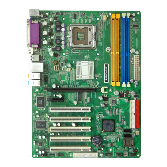
Page 8: Layout Diagram & Jumper Setting
1-4 Layout Diagram & Jumper Setting RJ45 PRINT PS/2 Mouse LINE-IN PS/2 Keyboard LINE-OUT VGA1 COM1 USB1 USBLAN K/B Power CPU FAN ON Jumper (JP1) PS2 KB/Mouse Port CPU Socket DDRII Socket X2 DDR Socket X2 PC99 Back Panel SFAN1 ATX Power USB Port Connector... - Page 9 Jumpers Jumper Name Description Page CMOS RAM Clear JBAT 3-pin Block Keyboard Power On Enable/Disabled 3-pin Block USB Power On Enable/Disabled 3-pin Block Connectors Connector Name Description Page ATXPWR Power Connector 24-pin Block P.21 ATX12V ATX 12V Power Connector 4-pin Block P.22 PS2KBMS PS/2 Mouse &...
-
Page 10: Chapter 2 Hardware Installation
Chapter 2 Hardware installation 2-1 Hardware installation Steps Before using your computer, you had better complete the following steps: 1. Check motherboard jumper setting 2. Install CPU and Fan 3. Install System Memory (DIMM) 4. Install Expansion cards 5. Connect IDE and Floppy cables, Front Panel /Back Panel cable 6. -
Page 11: Install Cpu
(2) Keyboard function Enabled/Disabled: JP1 (3) USB Power On function Enabled/Disabled: JP2 1-2 closed USB Power On Disable 2-3 closed USB Power On Enabled (Default) USB Power On Setting 2-3 Install CPU 2-3-1 Glossary Chipset (or core logic) - two or more integrated circuits which control the interfaces between the system processor, RAM, I/O devises, and adapter cards. -
Page 12: About Intel Pentium4 Lga 775 Cpu
scanners, and some digital cameras. Sound (interface) - the interface between the sound card or integrated sound connectors and speakers, MIC, game controllers, and MIDI sound devices. LAN (interface) - Local Area Network - the interface to your local area network. BIOS (Basic Input/Output System) - the program logic used to boot up a computer and establish the relationship between the various components. -
Page 13: Lga 775 Cpu Installation Guide
2-3-3 LGA 775 CPU Installation Guide Socket Preparation Opening the socket: Note: Apply pressure to the corner with right hand thumb while opening/closing the load lever, otherwise lever can bounce back like a “mouse trap” and WILL cause bent contacts (when loaded) Socket Load Plate Open... - Page 14 Visually inspect for bent contacts (Recommend at least 1stpass visual inspection) NOTE: Refer to the Handling and Inspection Module for 1stand 2ndpass inspection details. NOTE: Glove images are for illustrative purposes only. Please consult local safety guidelines for specific requirements NOTE: Recommend not to hold the load plate as a lever, instead hold at tab with left hand, removing the PnP cap with right hand...
- Page 15 775- Land Package Removal Open the Load Plate/Lever with both hands: With left hand index finger and thumb to support the load plate edge, engage PnP cap with right hand thumb and peel the cap from LGA775 Socket while pressing on center of PnP cap to assist in removal. Pick up 775-land LGA package: By Vacuum Pen: Place a minimum 9-mm cup at approximately the center of IHS.
- Page 16 Visually inspect socket contact array 1. First Pass Inspection Scan socket contact array at varying angles noting the presence of any foreign material If foreign material can’t be blown off by compressed air, or mechanical damage (Mode1 or 4) observed, reject the motherboard for further evaluation or socket replacement. 2.
- Page 17 • Align Fasteners with MB through-holes Inspection • Ensure cables are not trapped or interfere fastener operation • Ensure fastener slots are pointing straight out from heatsink Fastener Cap not Fastener flush resting against spring against MB Press Down Actuate fasteners (4 Places) •...
- Page 18 Intel Reference Thermal Solution Disassembly Rotate fastener cap. turn to un-lock Pull up fastener cap to un-seat 12 Disconnect fan cable from motherboard header Turn fastener caps (4) counter-clock wise 90degrees to the un-locked position • A flat-bladed screwdriver may be used if required Pull up on fastener caps to unseat Manually remove HS with gentle twist motion.
- Page 19 Remove the heatsink from the socket Gently push loose thermal interface material (TIM) to center of processor (pictures 2 and 3) Remove pieces with dry cloth (picture 4) Wipe with dry, lint-free cloth to remove most of the material (picture 5) Wet another lint-free cloth with isopropyl alcohol (IPA) and wipe to clean remaining material (picture 6) Be careful to remove material from gaps between processor and load plate...
- Page 20 Replacing Damaged Fasteners • To prevent damage, avoid setting the thermal solution with the prongs down − Set on heatsink side or with fan down • The plastic fasteners on the heatsink can be replaced. − Use Shop Intel to order spare fasteners −...
- Page 21 Tilt to remove Replacing Fasteners • To replace the fastener − Start with the white prong − Note the “keying” notch feature − Tilt the prong to insert into the heatsink leg. − Holding the white prong without bending it, push the black pin on from the bottom until you hear a single “click”...
-
Page 22: Install Memory
2-4 Install Memory The motherboards provide two 184-pin DUAL INLINE MEMORY MODULES (DIMM) and two 240-pin DDR2 DUAL INLINE MEMORY MODULES (DIMM). Valid Memory Configurations DIMM1 DIMM2 DIMM3 DIMM4 Total Memory DDR2 533/DDR2 400 SRAM Module 128M~1G DDR2 533/DDR2 DDR2 533/DDR2 400 SRAM Module 400 SRAM Module 128M~2G... -
Page 23: Expansion Card
2-5 Expansion Cards WARNING! Turn off your power when adding or removing expansion cards or other system components. Failure to do so may cause severe damage to both your motherboard and expansion cards. 2-5-1 Procedure For Expansion Card Installation 1. Read the documentation for your expansion card and make any necessary hardware or software setting for your expansion card such as jumpers. -
Page 24: Interrupt Request Table For This Motherboard
IMPORTANT! If using PCI cards on shared slots, make sure that the drivers support “Shared IRQ” or that the cards don’t need IRQ assignments. Conflicts will arise between the two PCI groups that will make the system unstable or cards inoperable. 2-5-4 PCI Express Slot This motherboard provides one 16-lane PCI Express slot which offers 4Gbyte/sec data transfer rate at each relative direction intended for Video Graphics Array, and one x1 PCI... -
Page 25: Connectors, Headers
2-6 Connectors, Headers 2-6-1 Connectors (1) Power Connector (24-pin block) : ATXPWR24P ATX Power Supply connector. This is a new defined 24-pins connector that usually comes with ATX case. The ATX Power Supply allows to use soft power on momentary switch that connect from the front panel switch to 2-pins Power On jumper pole on the motherboard. - Page 26 (2) ATX 12V Power Connector (4-pin block) : ATX12V This is a new defined 4-pins connector that usually comes with ATX Power Supply. The ATX Power Supply which fully support Pentium 4 processor must including this connector for support extra 12V voltage to maintain system power consumption. Without this connector might cause system unstable because the power supply can not provide sufficient current for system.
- Page 27 PS/2 Mouse PRINT USB1 LINE-IN LINE-OUT PS/2 Keyboard COM1 VGA1 (10) Floppy drive Connector (34-pin block): FDD This connector supports the provided floppy drive ribbon cable. After connecting the single plug end to motherboard, connect the two plugs at other end to the floppy drives. Pin 1 Floppy Drive Connector (11) Primary IDE Connector (40-pin block): IDE1...
-
Page 28: Headers
IDE2 Pin 1 Secondary IDE Connector • Two hard disks can be connected to each connector. The first HDD is referred to as the “Master” and the second HDD is referred to as the “Slave”. • For performance issues, we strongly suggest you don’t install a CD-ROM or DVD-ROM drive on the same IDE channel as a hard disk. - Page 29 AUDIO Pin 1 Line-Out, MIC Headers USB Port Headers (9-pin) : USB2/USB3 These headers are used for connecting the additional USB port plug. By attaching an option USB cable, your can be provided with two additional USB plugs affixed to the back panel.
- Page 30 SPEAK PWRLED Pin 1 Pin 1 JW_FP Pin 1 System Case Connections FAN Headers (3-pin) : SFAN1, SFAN2, CPUFAN These connectors support cooling fans of 350mA (4.2 Watts) or less, depending on the fan manufacturer, the wire and plug may be different. The red wire should be positive, while the black should be ground.
- Page 31 (10) In/Out Header: SPDIF (Module Optional) SPDIF Pin 1 SPDIF-Bracket Connector (11) IR infrared module Headers (5-pin) : IR This connector supports the optional wireless transmitting and receiving infrared module. You must configure the setting through the BIOS setup to use the IR function. Pin 1 IR infrared module Headers...
-
Page 32: Starting Up Your Computer
2-7 Starting Up Your Computer 1. After all connection are made, close your computer case cover. 2. Be sure all the switch are off, and check that the power supply input voltage is set to proper position, usually in-put voltage is 220V∼240V or 110V∼120V depending on your country’s voltage used. -
Page 33: Chapter 3 Introducing Bios
Chapter 3 Introducing BIOS The BIOS is a program located on a Flash Memory on the motherboard. This program is a bridge between motherboard and operating system. When you start the computer, the BIOS program gain control. The BIOS first operates an auto-diagnostic test called POST (power on self test) for all the necessary hardware, it detects the entire hardware device and configures the parameters of the hardware synchronization. -
Page 34: The Main Menu
3-3 The Main Menu Once you enter Award ® BIOS CMOS Setup Utility, the Main Menu (Figure 3-1) will appear on the screen. The Main Menu allows you to select from fourteen setup functions and two exit choices. Use arrow keys to select among the items and press <Enter> to accept or enter the sub-menu. -
Page 35: Standard Cmos Features
Load Optimized Defaults Use this menu to load the BIOS default values these are setting for optimal performances system operations for performance use. Load Standard Defaults Use this menu to load the BIOS default values for the stable performance system operation that are factory settings for normal use. -
Page 36: Advanced Bios Features
The time format is <hour><minute><second>. Primary Master/Primary Slave Secondary Master/Secondary Slave Press PgUp/<+> or PgDn/<–> to select Manual, None, Auto type. Note that the specifications of your drive must match with the drive table. The hard disk will not work properly if you enter improper information for this category. - Page 37 Anti-Virus Protection Allows you to choose the VIRUS Warning feature for IDE Hard Disk boot sector protection. If this function is enabled and someone attempt to write data into this area, BIOS will show a warning message on screen and alarm beep. Disabled (default) No warning message to appear when anything attempts to access the boot sector or hard disk partition table.
-
Page 38: Advanced Chipset Features
Typematic Rate (Chars/Sec) Sets the number of times a second to repeat a keystroke when you hold the key down. The settings are: 6, 8, 10, 12, 15, 20, 24, and 30. Typematic Delay (Msec) Sets the delay time after the key is held down before is begins to repeat the keystroke. The settings are 250, 500, 750, and 1000. -
Page 39: Clock/Drive Control
Selecting Enabled allows caching of the system BIOS ROM at F0000h-FFFFFh, resulting in better system performance. However, if any program writes to this memory area, a system error may result. The settings are: Enabled and Disabled. Video RAM Cacheable Select Enabled allows caching of the video BIOS, resulting in better system performance. However, if any program writes to this memory area, a system error may result. -
Page 40: Agp&P2P Bridge Control
3-6-2 AGP &P2P Bridge Control CMOS Setup Utility – Copyright(C) 1984-2004 Award Software AGP Timing Settings AGP Aperture Size 128M Item Help AGP 2.0 Mode AGP Master 1 WS Write Enabled AGP Master 1 WS Read Enabled Menu Level >> VGA Share Memory Size 64M------ Direct Frame Buffer... -
Page 41: Integrated Peripherals
3-7 Integrated Peripherals CMOS Setup Utility – Copyright(C) 1984-2004 Award Software Integrated Peripherals > VIA OnChip IDE Device Press Enter Item Help > VIA OnChip PCI Device Press Enter > Super IO Device Press Enter Init Display First PCIEX Menu Level > ↑↓→←... -
Page 42: Via Onchip Pci Device
OnChip IDE Channal0/Channel1 The integrated peripheral controller contains an IDE interface with support for two IDE channels. Select Enabled to activate each channel separately. The settings are: Enabled and Disabled. Primary/Secondary Master/Slave PIO The four IDE PIO (Programmed Input/Output) fields let you set a PIO mode (0-4) for each of the IDE devices that the onboard IDE interface supports. -
Page 43: Super Io Device
USB Host Controller Select Enabled if your system contains a Universal Serial Bus (USB) controller and you have a USB peripherals. The settings are: Enabled, Disabled. USB Keyboard Support Select Enabled if your system contains a Universal Serial Bus (USB) controller and you have a USB keyboard. -
Page 44: Power Management Setup
port with the ECP feature. After selecting it, the following message will appear: “ECP Mode Use DMA” at this time, the user can choose between DMA channels 3 to 1. The onboard parallel port is EPP Spec. compliant, so after the user chooses the onboard parallel port with the EPP function, the following message will be displayed on the screen: “EPP Mode Select.”... -
Page 45: Irq/Event Activility Detect
3-8-1 IRQ/Event Activility Detect CMOS Setup Utility – Copyright(C) 1984-2004 Award Software Wake Up Events PS2KB Wakeup Select Hotkey Item Help PS2KB Wakeup From S3/S4/S5 Disabled PS2MS Wakeup From S3/S4/S5 Disabled USB Resume from S3 Enabled Menu Level >> VGA OFF LPT&COM LPT/COM HDD&FDD... -
Page 46: 3-8-1.1 Irqs Activities
3-8-1.1 IRQs Activities CMOS Setup Utility – Copyright(C) 1984-2004 Award Software IRQs Activities Primary INTR Item Help IRQ3 (COM 2) Disabled IRQ4 (COM 1) Enabled IRQ5 (LPT 2) Enabled Menu Level >>> IRQ6 (Floppy Disk) Enabled IRQ7 (LPT 1) Enabled IRQ8 (RTC Alarm) Disabled... -
Page 47: Irq Resources
® unless you are using a Plug and Play operating system such as Windows 95/98. If you set this field to “manual” choose specific resources by going into each of the sub menu that follows this field (a sub menu is preceded by a “>”). The settings are: Auto(ESCD), Manual. -
Page 48: Pc Health Status
3-10 PC Health Status This section shows the Status of you CPU, Fan, Warning for overall system status. This is only available if there is Hardware Monitor onboard. CMOS Setup Utility – Copyright(C) 1984-2004 Award Software PC Health Status PC N.V.R Enabled Item Help Shutdown Temperature... -
Page 49: Thermal Throttling Option
3-11 Thermal Throttling Option CMOS Setup Utility – Copyright(C) 1984-2004 Award Software Miscellaneous Control CPU Thermal-Throttling Disabled CPU Thermal-Throttling Temp Item Help CPU Thermal-Throttling Duty 87.50% Beep Alarm Enabled Menu Level > ↑↓→← Move Enter:Select +/-/PU/PD:Value F10:Save ESC:Exit F1:General Help F5:Previous Values F6:Optimized Defaults F7:Standard Defaults... - Page 50 NB Voltage This item allows you to select value of Voltage for North Bridge Chipset. LDT Voltage This item allows you to select value of Voltage for LDT. Phoenix – AwardBIOS CMOS Setup Utility Power User Overclock Settings Current FSB Frequency 200MHZ PCIE Clock Item Help...
- Page 51 Phoenix – AwardBIOS CMOS Setup Utility Power User Overclock Settings Current FSB Frequency 200MHZ Item Help Current DRAM Frequency 200MHZ CPU Voltage at Next Boot Default CPU Ratio at next boot Default MEM Clock at Next Boot Auto Menu Level > CPU Clock at next Boot NB Voltage 200MHZ...
-
Page 52: Password Settings
3-13 Password Settings Phoenix – AwardBIOS CMOS Setup Utility Password Settings Item Help Set Supervisor Password Press Enter Set User Password Press Enter Menu Level > ↑↓→← Move Enter:Select +/-/PU/PD:Value F10:Save ESC:Exit F1:General Help F5:Previous Values F6:Optimized Defaults F7:Standard Defaults You can set either supervisor or user password, or both of them. -
Page 53: Chapter 4 Driver & Free Program Installation
Chapter 4 DRIVER & FREE PROGRAM INSTALLATION Check your package and there is A MAGIC INSTALL CD included. This CD consists of all DRIVERS you need and some free application programs and utility programs. In addition, this CD also include an auto detect software which can tell you which hardware is installed, and which DRIVERS needed so that your system can function properly. -
Page 54: Via 4 In 1 Install Via Service Pack 4 In 1 Driver
4-1 VIA 4 IN 1 Install VIA Service Pack 4 IN 1 Driver * The path of the file is X:\VIA\DRIVER\SETUP.EXE IDE : VIA ATAPI VENDOR SUPPORT DRIVER IS USED TO FIXED COMPATIBILITY ISSUE FOR IDE DEVICES AGPVXD : VIA AGPVXD DRIVER IS TO BE INSTALLED, IF YOU ARE USING AN AGP VGA CARD, VIAGART.VXD WILL PROVIDE SERVICE ROUTINES TO YOUR VGA DRIVER AND INTERFACE DIRECTLY TO HARDWARE, PROVIDING FAST GRAPHIC ACCESS... -
Page 55: Vga Install P4M890 Vga Driver
4-2 VGA install P4M890 VGA Driver For WINDOWS 9X/ME/NT4.0/2000/XP 1. Click VGA when MAGIC INSTALL MENU 2. Click NEXT When VIA/S3G UniChrome appears Family Display driver setup Appears Click Finish to Restart Computer 4-3 SOUND install VIA AC97’ Codec Audio Driver 1. -
Page 56: Lan Install Via Lan Controller Driver
Click Finish and Restart Windows Click Start→Program→Viny Deck→Viny Deck. Then Viny Deck Windows appears Speaker configuration setting 6. 2-ch Speaker position test Note: The path of the file For WIN98/NT4.0/WIN2K/XP is X:\CODEC\VIACODEC\SETUP.EXE Note: In Win2K/WinME users have to click Control Panel\System\Device Manager\ DVD\CD-ROM drives to Enabled digital CD Audio for the CD-ROM Device when use the SPDIF-Out digital signal. -
Page 57: Pc-Health Install Myguard Hardware Monitor Utility
PC-HEALTH Install MyGuard Hardware monitor Utility 1. Click PC-HEALTH when MAGIC INSTALL 2. Click Next when Install shield wizard Window MENU appears appears, Choose destination location and click Next, when the start copy file windows appear, click next 3. Select Finish after setup complete 4. -
Page 58: Pc-Cillin Install Pc-Cillin2006 Anti-Virus Program
4-6 PC-CILLIN Install PC-CILLIN 2006 Anti-virus program 1. Click PC-CILLIN when MAGIC 2. Please select “Install program” when the INSTALL MENU appears "Trend Micro internet security" installshield wizard windows appears This is license agreement, select "I Accept Click NEXT or choose Change to change the the terms"... -
Page 59: Usb2.0
4-7 USB2.0 Install VIA USB2.0 DEVICE DRIVER 1. Click USB2.0 when MAGIC INSTALL 2. When USB2.0 Setup Program Appear, MENU Appear Click NEXT Note: Please Install Microsoft Service Pack 1 in Windows XP OS Before you Install VIA USB2.0 Device Driver. 3. -
Page 60: Sata Install Via Serial Ata
4-8 SATA Install VIA Serial ATA 1. Click SATA when MAGIC INSTALL 2. When license agreement appear, choose I MENU appears agree and click NEXT 3. Select you want to install driver 4. Review install driver and utility component, then click NEXT 5. -
Page 61: How To Disable On-Board Sound
STEP 2: After booting OS insert the bundle CD in your CD-ROM STEP 3: Copy all the files from \VIA\VIASATA\DriverDisk to floppy diskette Once you have the SATA driver diskette ready, you may start to install Windows XP or Windows 2000 on your System. Installation of Windows XP/ Windows 2000 For installation of Windows XP or Windows 2000, please insert Windows XP or Windows 2000 CD into the CD-ROM drive.
Need help?
Do you have a question about the P890DAP-LF and is the answer not in the manual?
Questions and answers