Table of Contents
Advertisement
Quick Links
Advertisement
Table of Contents

Related Manuals for Hanwha Vision QNV-C6083R


Summary of Contents for Hanwha Vision QNV-C6083R
- Page 1 NETWORK CAMERA User Manual QNV-C6083R QNO-C6083R...
- Page 2 Network Camera User Manual Copyright ©2024 Co., Ltd. All rights reserved. Hanwha Vision Trademark Each of trademarks herein is registered. The name of this product and other trademarks mentioned in this manual are the registered trademark of their respective company. Restriction Copyright of this document is reserved.
- Page 3 15. This product is intended to be supplied by a UL Listed Power Supply Unit marked “Class 2” or “LPS” or “PS2” and rated from PoE (48Vdc), 0.2A. (QNV-C6083R) EXPLANATION OF GRAPHICAL SYMBOLS 16.
- Page 4 overview Class construction Please read the following recommended safety precautions carefully. An apparatus with CLASS construction shall be connected to a MAINS socket outlet with a ~ Do not place this apparatus on an uneven surface. protective earthing connection. ~ Do not install on a surface where it is exposed to direct sunlight, near heating equipment or heavy cold area.
-
Page 5: Table Of Contents
CONTENTS OVERVIEW NETWORK CONNECTION AND Important Safety Instructions Connecting the Camera Directly to Local Recommended PC Specifications Area Networking SETUP Recommended Micro SD/SDHC/SDXC Connecting the Camera Directly to a DHCP Memory Card Specifications Based DSL/Cable Modem NAS recommended specs Using Device Manager Optional Accessories for Installation Automatically searching camera Configuring IP address... -
Page 6: Recommended Pc Specifications
overview RECOMMENDED PC SPECIFICATIONS NAS RECOMMENDED SPECS ~ CPU : Intel(R) Core(TM) i7 3.4 GHz or higher ~ Recommended capacity : 200GB or higher is recommended. ~ RAM : 8G or higher ~ For this camera, you are recommended to use a NAS with the following manufacturer’s specs. ~ Recommended browser: Chrome Recommended products : QNAP NAS, Synology NAS ~ Supported browsers: Chrome, Safari, Firefox, MS Edge(chromium based) - Page 7 Vandal Dome Camera Bullet Camera QNV-C6083R QNO-C6083R English _7...
-
Page 8: Optional Accessories For Installation
Wall Mount and Pole Mount Hanging Mount Gang Plate Accessory cable Conduit adaptor (Direct Assembly) Mount SBP-140WMW (Indoor Wall&Pole Mount) SPP-C7400 SBV-140BW (Back Box) QNV-C6083R SBP-300WMW (Wall Mount) SBP-060BA SBP-140HMW * SBP-300PMW2 required for SBD-140PMW SBP-300PMW2 pole installation (Pole Mount) SBV-140TMW SPP-C1900... - Page 9 Ceiling Mount Model name Corner Mount Parapet Mount Installation Box Assembly Individual Parts SBP-180CMB SBP-300KMW1 SBP-300LMW QNV-C6083R SBP-C15P SBP-180CMS SBP-300NBW (Ball Head) SBP-150CMI SBP-300CMTW SBP-156CMW SBP-300CMTS SBP-300CMI SBP-150CMP SBP-156KMW (Telescopic) (Ball Head) SBP-300CMW1 (Telescopic) SBP-300CMP SBP-900CMW SBP-900CMP SBP-140CMB SBP-156LMW1 SBD-140KMB...
-
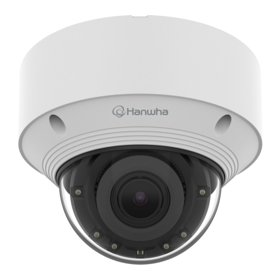
Page 10: Vandal Dome Camera
WHAT’S INCLUDED AT A GLANCE As for each sales country, accessories are not the same. Mount-plate Camera-body Wiring hole cover Dome-cover <QNV-C6083R> IR LED Micro HDMI port Illumination Sensor Lens Option (not included) Reset button SPP-C7400 SPP-C1900 Micro USB Use installation screws of at least M4, L30 for the installation of this product. -
Page 11: Installation
INSTALLATION 2. Remove the camera body by turning the mount plate fastening screws counterclockwise. Note that it is not necessary to loosen the screws completely. The camera jack connected to the external cable is not waterproof. You are recommended to install this product below the edge of eaves to prevent the cable from being externally exposed. - Page 12 vandal dome camera Inserting a Micro SD card Removing a Micro SD card Insert the micro SD card into the micro SD card slot on the camera body in the arrow direction. Gently press down on the exposed end of the Micro SD card as shown in the diagram to eject the Micro SD card from the slot.
- Page 13 Installation (mount plate) When connecting cables from the side, first remove the wiring hole cover of the dome cover. [Directly installing on wall/ceiling] 1. Place the mount plate on the desired location considering the direction to be monitored, mark the locations for the screw holes and cable holes, and then drill the holes.
- Page 14 vandal dome camera [Installing using pipe] Installation (camera body) 1. When connecting and installing a pipe, you can remove the wiring hole cover of the dome cover. Use a cable bushing compliant with the network cable to be connected. As shown in the picture, remove the wiring hole cover of the lower dome cover and install the pipe Camera main: use a cable with the diameter of Ø5 to Ø6.5 according to the instructions below.
- Page 15 4. For waterproof protection, pull down the cable below the cable bushing as shown in the figure below. 6. Connect the network cable connector to the PoE port of the camera body. 5. Insert the cable bushing of the network cable into the camera body. [Installing the micro HDMI cable (separately sold)] 1.
- Page 16 vandal dome camera 2. Insert the cable bushing of the micro HDMI cable into the camera body. [Installing audio/alarm cables (separately sold)] 1. Remove the cable bushing next to the PoE port from the camera body. 3. Connect the HDMI cable connector to the micro HDMI port of the camera body. 2.
- Page 17 3. Connect the audio/alarm cable connector to the audio/alarm cable port of the camera body. 5. Adjust the lens to the desired direction with reference to “Adjusting the monitoring direction for the camera” section. (page 19) If you tilt the lens, you may need to adjust the lens as this may block the screen. Connect a monitoring device to the USB port and then monitor and adjust it.
- Page 18 vandal dome camera Waterproofing of cable connections Be careful not to alter the monitoring direction of your camera. When installing the camera, please waterproof it with waterproof butyl rubber tape (can be purchased in stores) so that water does not leak from the gap of the cable connected to the outside. 1.
-
Page 19: Adjusting The Monitoring Direction For The Camera
ADJUSTING THE MONITORING DIRECTION FOR THE CAMERA Tilt Lens Rotation ` Adjusting the monitoring direction You can adjust the camera direction only when the camera is fixed on the ceiling. At this time, rotating the main body of the camera in the left and right direction is called PAN, and adjusting the angle of the camera is called TILT. -
Page 20: Bullet Camera
bullet camera WHAT’S INCLUDED AT A GLANCE As for each sales country, accessories are not the same. Sunshield fixing screw Sunshield <QNO-C6083R> Camera body Port box PoE port Use installation screws of at least M4, L30 for the installation of this product. Reset button Audio I/O port... -
Page 21: Installation
INSTALLATION Removing a Micro SD card Gently press down on the exposed end of the Micro SD card as shown in the diagram to eject the Micro SD card from the slot. The camera jack connected to the external cable is not waterproof. You are recommended to install this product below the edge of eaves to prevent the cable from being externally exposed. - Page 22 bullet camera Installation 4. Loosen the fixing screws of each control part to adjust the monitoring direction of the camera. Note that it is not necessary to loosen the screws completely. [Directly installing on wall/ceiling] Connect a monitoring device to the USB port and then monitor and adjust it. 1.
- Page 23 5. Assemble the sunshield on the camera body with the provided sunshield fixing screws. 1.5 ~ 2 N·m (1.1 ~1.47 lb·ft) <Tilt> When adjusting the camera monitoring direction, loosen the corresponding fixing screws, adjust the camera, and then tighten the screws. Forcibly adjusting the camera while the screws are fastened may cause scratches and malfunction. English _23...
- Page 24 bullet camera How to connect the RJ45 waterproof cable to a LAN cable Waterproofing of cable connections When installing the camera, please waterproof it with waterproof butyl rubber tape (can be purchased in 1. Insert it through the arrow direction. stores) so that water does not leak from the gap of the cable connected to the outside.
-
Page 25: Installation & Connection
The Micro USB port of the product is provided for easier installation, and is not recommended for monitoring purposes. Ethernet <QNV-C6083R> The Micro USB port of the product is provided for easier installation, and is not recommended for monitoring purposes. - Page 26 installation & connection Powering and networking Connecting WiFi Connect the PoE device with the PoE port of the camera. Camera Setup 1. Connect OTG adapter (5-pin) and WiFi dongle to the micro USB port. Connect and use a PoE enabled router. Use a PoE device that complies with the IEEE 802.3af standard.
- Page 27 Impedance: 1,500 Ω Network Sensitivity: -40±3 dB (7.1-14.1 mV) The audio/alarm cables for QNV-C6083R need to be purchased separately. Speaker Microphone 1. Connect the MIC port of the camera with the microphone or LINE OUT port of the amplifier that the microphone is connected to.
- Page 28 Refer to the “Alarm Out Wiring Diagram” when connecting devices that exceed the voltage and current specifications. The audio/alarm cables for QNV-C6083R need to be purchased separately. QNV-C6083R SIGNAL LINE - BLACK : GND / ORANGE : ALARM IN / BROWN : ALARM OUT 28_ installation & connection...
-
Page 29: Connecting The Camera Directly To Local Area Networking
network connection and setup CONNECTING THE CAMERA DIRECTLY TO A DHCP BASED DSL/CABLE You can set up the network settings according to your network configurations. MODEM CONNECTING THE CAMERA DIRECTLY TO LOCAL AREA NETWORKING Connecting to the camera from a local PC in the LAN INTERNET 1. -
Page 30: Using Device Manager
If using a Broadband Router ~ IP Address : Enter an address falling in the IP range provided by the Broadband Router. Device manager program can be downloaded from <Support>-<Online Tool> menu at Hanwha Vision website ex) 192.168.1.2~254, 192.168.0.2~254, (https://www.HanwhaVision.com). -
Page 31: Manually Registering Camera
~ Example of the Dynamic IP environment configure the IP. QNV-C6083R - If a Broadband Router, with cameras connected, is assigned an IP address by the DHCP server 2. Click < + > at the main page of device manager. -
Page 32: Port Range Forward (Port Mapping) Setup
network connection and setup PORT RANGE FORWARD (PORT MAPPING) SETUP Setting up Port Range Forward for several network cameras ~ You can set a rule of Port Forwarding on the Broadband Router device through its configuration web page. If you have installed a Broadband Router with a camera connected, you must set the port range forwarding on the ~ A user can change each port using the camera setting screen. -
Page 33: Connecting To The Camera From A Shared Local Pc
CONNECTING TO THE CAMERA FROM A SHARED LOCAL PC 1. Run device manager. It will scan for connected cameras and display them as a list. 2. Double-click a camera to access. The Internet browser starts and connects to the camera. Access to the camera can also be gained by typing the camera’s IP address in the address bar of the Internet browser. -
Page 34: Connecting To The Camera
web viewer web viewer CONNECTING TO THE CAMERA Connecting via Bonjour 1. Run the client or operating system in support of the Bonjour protocol. Normally, you would 2. Click the camera name for search. In the Mac operating system, click the camera name searched from the Bonjour tab of Safari. 1. -
Page 35: Password Setting
PASSWORD SETTING CAMERA WEB VIEWER SETUP When you access the product for the first time, you must register the 1. Click the [Setup ( )] icon. login password. 2. The Settings window appears. 3. You can configure settings for the camera’s basic information, video, audio, network, event, analysis, and For a new password with 8 to 9 characters, you must use at least 3 system over the network. -
Page 36: Troubleshooting
appendix TROUBLESHOOTING PROBLEM SOLUTION PROBLEM SOLUTION Voice is not recorded even though When an Windows 10 user accesses ~ You must enable the <Audio In> check box in <Basic> - <Video Profile>. ~ This is what happens when microphone driver has been set to Realtek driver. audio input settings are configured. - Page 37 Operation of this equipment in a residential area is likely to cause harmful interference in which case the user will be required to correct the interference at his own expense. Hanwha Vision cares for the environment at all product manufacturing stages, and is taking measures to provide customers with more environmentally friendly products.
Need help?
Do you have a question about the QNV-C6083R and is the answer not in the manual?
Questions and answers