Table of Contents
Advertisement
Quick Links
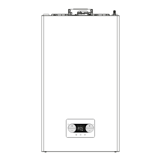
VIBE MAX
High efficiency system boiler
5 0 8
.
Users Instructions
Installation &
Servicing
Instructions
VIBE MAX 20S G.C. N° 41-364-19
VIBE MAX 25S G.C. N° 41-364-20
THESE INSTRUCTIONS
TO BE RETAINED
BY USER
Vokèra is a licensed member of the Benchmark scheme
which aims to improve the standards of installation and
commissioning of domestic hot water systems in the UK.
Advertisement
Table of Contents

Subscribe to Our Youtube Channel
Related Manuals for Riello Vokera VIBE MAX Series


Summary of Contents for Riello Vokera VIBE MAX Series
- Page 1 VIBE MAX High efficiency system boiler Users Instructions Installation & Servicing Instructions VIBE MAX 20S G.C. N° 41-364-19 VIBE MAX 25S G.C. N° 41-364-20 THESE INSTRUCTIONS TO BE RETAINED 5 0 8 BY USER Vokèra is a licensed member of the Benchmark scheme which aims to improve the standards of installation and commissioning of domestic hot water systems in the UK.
- Page 2 1. THINGS YOU SHOULD KNOW ........... 2 SECTION 7 - WIRING DIAGRAMS ............. 35 2. GETTING STARTED ..............5 SECTION 8 - LPG INSTRUCTIONS ..........36 3. WHAT IF ..................7 Commissioning checklist ............37 SECTION 1 - DESIGN PRINCIPLES AND OPERATING Benchmark ................38-41 SEQUENCE ..................
-
Page 3: Frost Protection System
FROST PROTECTION SYSTEM The VIBE MAX is equipped with a built-in frost protection system, this enables the boiler to over-ride the time controls – even if switched off – and operate the burner and/or pump, should the temperature drop below 5°C. In particular the burner will be in ON status until the appliance temperature reaches 35°C. - Page 4 1.10 SETTING PASSWORD, ACCESS AND PARAMETER MODIFICATION In the manual, whenever necessary - enter the password to access the parameters 1 88 - choose, modify and/or confirm parameters follow the sequences involved - see table - for more immediate action Actions Sequence password entry...
-
Page 5: Getting Started
1.11 USER PROGRAMMABLE PARAMETERS Value USER Password Value set in Personalised level the factory values PARAMETERS min max SETTINGS MEASUREMENT UNIT USER BUZZER USER 1.12 INFO MENU interface automatically quits the INFO menu if iI 0 iI 0 0 1 3 iI 0 no key is pressed for 60 sec... -
Page 6: Switching Off For Lengthy Periods
SETTING THE HEATING SETPOINT SWITCHING OFF FOR LENGTHY PERIODS If the boiler is not used for a long time, the following operations must be carried out: 0 0 6 0 5 6 ƒ set the OFF status ƒ isolate the appliance from the electrical supply ƒ... -
Page 7: What If I Suspect A Gas Leak
Fault A41 In the presence of alarms A40 or A41, from revision 9 of If the pressure value falls below the 0.3 bar safety value, the the board software available in the INFO menu (“1.12 INFO boiler shows the fault code A41 for a transitory time of 10 menu”, item I035), the display of the anomaly code (5sec) al- min. -
Page 8: Installation And Servicing Instructions
INSTALLATION AND SERVICING INSTRUCTIONS INTRODUCTION All installers are asked to follow the Benchmark Scheme by VIBE MAX boiler complies with basic requirements of the adhering to the Code of Practise, details of which can be ob- following Directives: tained from www.benchmark.org.uk. - Regulation (EU) 2016/426;... -
Page 9: Design Principles And Operating Sequence
DESIGN PRINCIPLES AND OPERATING SEQUENCE PRINCIPLE COMPONENTS When the request for heat has been satisfied the appliance pump and fan may continue to operate to dissipate any residual • A fully integrated electronic control board featuring electronic heat within the appliance. temperature control, anti-cycle control, pump over-run, self- diagnostic fault indicator, full air/gas modulation SAFETY DEVICES... -
Page 10: Technical Data
TECHNICAL DATA Central Heating VIBE MAX 20S VIBE MAX 25S Heat input (kW) 20.00*** 25.00*** Maximum heat output (kW) 60/80°C 19.38 24.38 Minimum heat output (kW) 60/80°C 2.94 3.79 Maximum heat output (kW) 30/50°C 20.92 26.78 Minimum heat output (kW) 30/50°C 3.04 4.09 Heat input range rated (Qn) (kW) - Page 11 Parameter Symbol Unit VIBE MAX 20S VIBE MAX 25S Seasonal space heating energy efficiency class Water heating energy efficiency class Rated heat output Pnominal Seasonal space heating energy efficiency ηs Useful heat output At rated heat output and high-temperature regime (*) 19,4 24,4 At 30% of rated heat output and low-temperature regime (**)
- Page 12 PUMP DUTY Fig. 4 shows the flow-rate available – after allowing for pressure loss through the appliance – for system requirements. When using this graph, apply only the pressure loss of the system. Variable speed circulator The modulating circulator function is active only in the heating function. The modulating circulator function is only applied to the boiler circulator and not to circulators of any connected external devices (e.g.
-
Page 13: General Requirements (Uk)
GENERAL REQUIREMENTS (UK) BS 5440 PART 1 FLUES BS 5440 PART 2 FLUES & VENTILATION BS EN 12828 DESIGN FOR WATER-BASED HEATING SYSTEMS BS 5546 INSTALLATION OF GAS HOT WATER SUPPLIES FOR DOMESTIC PURPOSES BS 6798 INSTALLATION OF BOILERS OF RATED INPUT NOT EXCEEDING 60kW BS 6891 LOW PRESSURE INSTALLATION PIPES APPLICATION, SELECTION, AND INSTALLATION OF EXPANSION VESSELS AND... -
Page 14: Electrical Supply
3.10 WATER TREATMENT 3.6.6 FILLING POINT A method for initial filling of the system and replacing water lost Vokèra recommend that an inhibitor - suitable for use with during servicing etc. directly from the mains supply, is provided stainless-steel heat exchangers - is used to protect the boiler (see Fig. - Page 15 3.6.6E FILLING POINT Where the installation of the appliance will be in an unusual location special procedures may be necessary, refer to I.S. 813 A method for initial filling of the system and replacing water lost for detailed guidance on this aspect. during servicing etc.
-
Page 16: Installation
INSTALLATION NOTE FITTING THE FLUE Please refer to 3 - 3E and use the appropriate PPE when This appliance incorporates a ‘click-fit’ flue connection at the carrying out any of the actions or procedures contained within top of the appliance. this section. -
Page 17: Concentric Vertical Flue
with the ‘click-fit’ and insert it into the ‘click-fit’ until it clicks into position (this is when the tabs at points ‘A’ are located in the groove of the flue bend connector). Both screws (C) should now be tightened. NOTE Fit the internal (white) trim to the flue assembly prior to connecting the flue pipe to the bend. -
Page 18: Connecting The Gas & Water
NOTE: depending on system requirements, it may necessary to increase the size of the flow & return pipe work after the service valve connections. 4.3.3 SAFETY VALVE Connect the safety valve connection pipe to the safety valve outlet and tighten. The discharge pipe must have a continuous fall away from the appliance to outside and allow any water to drain away thereby eliminating the possibility of freezing. -
Page 19: Electrical Connections
CASING REMOVAL Note: if the condensation exhaust system is exposed to the risk of frost, always provide an adequate level of insulation of the pipe To gain internal access to the appliance you must first remove and consider any increase in the diameter of the pipe itself. the casing, proceed as outlined below: •... -
Page 20: Commissioning And Operation
COMMISSIONING & OPERATION FINAL FLUSHING OF THE HEATING NOTE: please refer to 3 - 3E and use the appropriate PPE when carrying out any of the actions or procedures contained SYSTEM within this section. The system shall be flushed in accordance with BS 7593 (I.S. 813 ROI). -
Page 21: Control Panel
CONTROL PANEL Your boiler is equipped with a large LCD display that indicates the appliance operating status. Each time the keys are pressed, the boiler makes a sound signal (Buzzer); it is possible through parameter 006 Buzzer to manage the enabling (1) or disabling (0) of the sound. Note: values in thousands are displayed/100, for example 6500 rpm = 65.0 5 0 8 A and B... -
Page 22: User Level
0 04 0 06 1 88 USER LEVEL 2 sec P AS 0 00 1 88 INSTALLER (18) and SERVICE (53) LEVEL second long press 0 04 1 88 1 88 password setting first menu parameter confirm password access to the chosen parameter parameter choice confirmation of the new value and return to previous level... -
Page 23: Initial Lighting
5.10 INITIAL LIGHTING 5.14 SETTING THE HEATING SETPOINT WITH AN EXTERNAL PROBE ƒ Position the system’s main switch to the “on” position. ƒ Open the gas tap to allow the fuel to flow. If an external probe is connected (optional) and temperature ƒ... -
Page 24: Screed Heater Function
5.16 SCREED HEATER FUNCTION If the calculation produces an intermediate value between two curves, you are advised to choose the thermoregulation curve With the system at a low temperature, the “screed heater” closest to the value obtained. function enables a heating request with a delivery setpoint of Example : if the value obtained from the calculation is 1.3, this 20°C in the initial zone. -
Page 25: Gas Valve Calibration
The displayed value refers to the number of revolutions divi- and minimum output, maximum heating and slow ignition must be ded by 100. made in the sequence indicated, and by qualified personnel only: ƒ power up the boiler ƒ Set the maximum rpm value ƒ... -
Page 26: Error Code
Record the new set value in the table on the back cover of If the correct operating conditions have been restored, the this manual. For subsequent controls and adjustments, refer boiler will start up again automatically. In the presence of a re- to the set value. - Page 27 5.22 SAFETY STOP 5.26 TEMPORARY SWITCH-OFF If faults arise during ignition or operation, the boiler makes a In the event of temporary absences (weekends, short breaks, “SAFETY STOP”. The display shows the error code in ques- etc.) set the status of the boiler to OFF. tion.
-
Page 28: Programmable Parameters
5.28 PROGRAMMABLE PARAMETERS A list of the programmable parameters is given below: USER (level always available) and INSTALLER (access with pass- word 18); for a detailed explanation of the parameters, refer to paragraph "5.29 Parameters description". Some information might not be available depending on the access level, machine status or system configura- tion. -
Page 29: Parameter Description
Value Password Value set in Personalised SERVICE PARAMETERS level the factory values TECHNICAL 0 (the value automatically changes ALARM HISTORY ACTIVATION SERVICE to 1 after 2 hours of operation) SERVICE CALL FUNCTION SERVICE SERVICE DEADLINE SERVICE HIGH EFFICIENCY MODE SERVICE CONNECTIVITY BUS 485 CONFIG. - Page 30 Activates the “night-time compensation” function. The default value is 0. Set at 1 to activate the function. See paragraph “5.15 Setting the thermoregulation” for more details about this function. Frequency with which the value of the calculated outdoor temperature for thermoregulation is updated, a low value for this value will be used for buildings that have little insulation.
-
Page 31: Final Checks
5.31 FINAL CHECKS In case of stubborn deposits of combustion products on • ENSURE ALL TEST NIPPLES ON THE APPLIANCE GAS the surface of the exchanger, clean by spraying natural VALVE ARE TIGHT AND CHECKED FOR TIGHTNESS. white vinegar, taking care NOT to damage the retarder •... - Page 32 Replacing the burner insulating panel ƒ Unscrew the ignition/detection electrode fixing screws and remove it. ƒ Remove the burner insulating panel (D) by inserting a blade underneath the surface (as shown in the figure). ƒ Remove any fixing glue residue. ƒ...
-
Page 33: Replacement Of Components
SECTION - SERVICING INSTRUCTIONS GENERAL UNSCHEDULED MAINTENANCE The appliance incorporates software that monitors the Once the appliance has been serviced, the benchmark Service operating conditions of the appliance, and will record any Record must be completed. ‘unusual usage conditions’ that will affect the requirement to For UK only remove and clean the burner/heat exchanger assembly. -
Page 34: Wiring Diagrams
WIRING DIAGRAMS NOTE Please refer to 3 - 3E and use the appropriate PPE when carrying out any of the actions or procedures contained within this section. EXTERNAL WIRING The appliance can be used with the following controls: twin- channel programmers or single channel timers (refer to adjacent diagrams for details). -
Page 35: Functional Diagram
FUNCTIONAL DIAGRAM P.T. F.O.H.T. F.T. R.S. F Lv -t° -t° F.S. -t° BE11 black black AKJ01 black (-) orange (A) yellow (B) red (+24 Vdc) F=4A T ACC1 S.S.E. GAS VALVE 230 V F1= 3.15A F - A B + CE4 (removable connector positioned under shelf) pink... -
Page 36: Lpg Instructions
LPG INSTRUCTIONS RELATED DOCUMENTS BS 6798 INSTALLATION OF BOILERS OF RATED INPUT NOT EXCEEDING 60 kW BS EN 12828 DESIGN FOR WATER-BASED HEATING SYSTEMS BS 5446 INSTALLATION OF GAS HOT WATER SUPPLIES FOR DOMESTIC PURPOSES BS 5440 PARTS 1 & 2 FLUES & VENTILATION BS 6891 SPECIFICATION FOR THE INSTALLATION AND MAINTENANCE OF LOW PRESSURE GAS INSTALLATION PIPEWORK OF UP TO 35 mm... - Page 37 COMMISSIONING: CO AND COMBUSTION RATIO CHECK BEFORE CO AND COMBUSTION RATIO CHECK NOTE The installation instructions should have been followed, gas type verified and gas supply pressure/rate checked as required The air/gas ratio valve is factory-set and must not be prior to commissioning.
- Page 38 Benchmark Commissioning & Warranty Validation Service Record It is a requirement that the boiler is installed and commissioned to the manufacturers’ To instigate the boiler warranty the boiler needs to be registered with the manufacturer within one month of the installation. The warranty rests with the end-user (consumer), and they should be made aware it is ultimately their responsibility to register with the manufacturer, within the allotted time period.
-
Page 39: Condensate Disposal
GAS BOILER SYSTEM COMMISSIONING CHECKLIST & WARRANTY VALIDATION RECORD Address: Boiler make and model: Boiler serial number: Commissioned by (PRINT NAME): Gas Safe registration number: Company name: Telephone number: Company email: Company address: Commissioning date: Heating and hot water system complies with the appropriate Building Regulations? Time, temperature control and boiler interlock provided for central heating and hot water Boiler Plus requirements (tick the appropriate box(s)) Weather compensation... - Page 40 SERVICE & INTERIM BOILER WORK RECORD It is recommended that your boiler and heating system are regularly serviced and maintained, in line with manufacturers’ instructions, and that the appropriate service / interim work record is completed. Service provider When completing a service record (as below), please ensure you have carried out the service as described in the manufacturers’ instructions. Always use the SERVICE/INTERIM WORK ON BOILER SERVICE/INTERIM WORK ON BOILER Date:...
- Page 41 SERVICE & INTERIM BOILER WORK RECORD It is recommended that your boiler and heating system are regularly serviced and maintained, in line with manufacturers’ instructions, and that the appropriate service / interim work record is completed. Service provider When completing a service record (as below), please ensure you have carried out the service as described in the manufacturers’ instructions. Always use the SERVICE/INTERIM WORK ON BOILER SERVICE/INTERIM WORK ON BOILER Date:...
- Page 42 Vokèra Warranty Terms and Conditions Vokèra Ltd offer customers the comfort of a parts and labour warranty repair service subject to the following terms and conditions. Vokèra Ltd only obligation under the guarantee shall be to repair or replace the faulty appliance at Vokèra Ltd discretion.
- Page 43 Health & Safety: Engineers will only attend to boiler products where it is considered by the engineer that the installation does not pose a risk to health and safety. A permanently fixed access ladder must service installations in lofts or attics. Adequate lighting and permanently fixed flooring must also be available.
- Page 44 RANGE RATED - EN 15502-1 The max CH input of this boiler has been adjusted to_____ kW, equivalent to _____ rpm max CH fan speed. Date___/____/____ Signature _____________________ Boiler serial number _____________________ Registered address: Vokèra Ltd Borderlake House Unit 7 Riverside Industrial Estate London Colney Herts AL2 1HG www.vokera.co.uk...
Need help?
Do you have a question about the Vokera VIBE MAX Series and is the answer not in the manual?
Questions and answers