Table of Contents

Related Manuals for Haier HP300S2-F7


Summary of Contents for Haier HP300S2-F7
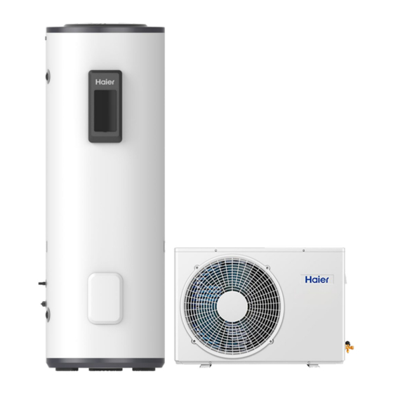
- Page 1 Heat Pump Water Heater Operation and Installation Manual Model HP300S2-F7 Please read this manual carefully prior to your use of this water heater. The appearance of the water heater shown in this manual is for reference only.
-
Page 2: Table Of Contents
9. Checking and maintenance ....................36 10. Faults and protection ......................37 Dear users of Haier, Thank you for choosing Haier products. Please read this manual carefully and follow the operation and safety instructions to ensure the best installation and utilization of the product. -
Page 3: Safety Instructions
Safety instructions (to be followed at all times) Interpretation of marks and symbols Failure to follow these instructions may lead to serious appliance malfunction and risks harm to the user. Instructions with this warning mark shall be strictly followed during operation. T h e y r elate to the safety of users. - Page 4 Safety instructions (to be followed at all times) The outlet water temperature of a This appliance must be installed water heater may be higher than with an isolation switch to the the temperature indicated on the power supply. This switch must display.
- Page 5 Safety instructions (to be followed at all times) The PTR valve must be Water heaters shall be operated every six months to equipped with a dedicated remove lime deposits and power line and residual ensure it is free from blockages. current circuit breakers.
-
Page 6: Instructions On Transportation And Storage
Instructions on transportation and storage 1. During transportation or storage, the heat pump water heater should remain in its packaging. This will prevent possible damage to appearance and performance of the product. 2. During transportation or storage, the heat pump unit and the cylinder should remain in the upright position. -
Page 7: Technical Parameters
Packaging dimension (heat pump unit) (917*348*597)mm Net/Gross weight (tank unit) 86/97kg Refrigerant pair-coil sizes 1/4”(6.35mm) – 3/8”(9.52mm) Refrigerant connections 7/16-20 UNF – 5/8-18 UNF Net/Gross weight (heat pump unit) 30/33kg * The COP and noise level data was tested in Haier lab. -
Page 8: Description Of Parts And Components
Description of parts and components Heat pump structure Hot water outlet valve UI cover Handle Electrical cover Refrigerant Refrigerant inlet outlet Cold water Drain outlet. connection Electrical cover Air grille Shield HP300S2-F7... - Page 9 Description of parts and components Exploded view (tank unit) Description Service lid Temperature controller Water tank temperature sensor Seal ring Back shell of wire controller Display plate rear shell Display plate front shell Front shell of wire controller Display panel cover 10 Electric heating element Electrical room rear housing...
- Page 10 Description of parts and components Exploded view (heat pump unit) Description Description Air grille Compressor Front cover Expansion valve Evaporator Controller panel Top Cover Bottom Cover Right Cover Handle Four-way valve Shield Accessories (heat pump unit) Heat pump Condensate Drain Wrapping Packing Through the...
-
Page 11: Installation Instructions
Installation instructions Installation precaution - Do not install the water heater in a location that exposes it to gas, vapors, or dust. - Install the cylinder and heat-pump unit on a flat, solid surface. The surface or base must be able to support the weight of the appliance, and condensate must be able to drain freely. - Page 12 Installation instructions Installation dimensions Unit: mm Model THP300S2-F7 1410 1694 Model EHP50S2-F7...
- Page 13 Installation instructions Installation clearances >200mm Outdoor unit >600mm...
- Page 14 Installation instructions Tools for the connection of refrigerant lines a) Group manometer suitable for use with R32, with charge and vacuum tubes. b) Vacuum pump. c) Torque wrenches for nominal diameter of 7/16-20UNF and 5/8 -18UNF sizes on both sides to respond to the measures of the pipe unions. d) Flaring clamp ø...
- Page 15 Installation instructions Connecting the tank unit a) Shape the pipes according to the route required. b) Remove the threaded brass flare nuts(A) on the tank unit and store them. c) Check that that the pipes and fittings are clear of impurities. d) Cut the pipe to the fixed length using a pipe cutter and avoiding any deformation.
- Page 16 Installation instructions Connecting the heat pump unit When making the connections, follow local standards and regulations. Remove the caps from 2- and 3-way valves. Fit the flare nuts of the pump onto the on the pipes, screw the flare nuts to connect the heat pump unit with the same method described for the cylinder.
- Page 17 Installation instructions Charging the appliance If you are adding R32 gas in the circuit, you will need: - Electronic scales for refrigerant charging with sensitivity 1g. During installation: a) Connect the manometer to the low-pressure service valve and connect the refrigerant cylinder to the center tap of the manometer.
- Page 18 Installation instructions Plumbing installation Plumbing installation must be compliant with AS/NZS3500.4 and the Plumbing Code of Australia (PCA). 1 . The plumbing connections for this appliance must be installed: a. by licensed trades people. b. in accordance with all local codes and regulations and standards including AS/NZS3500.4, AS/NZS 3000, and the Plumbing Code of Australia (PCA).
- Page 19 Installation instructions Pipeline installation diagram Thermostatic mixing valve Hot water outlet PTR valve drain line Isolating non-return Pressure valve ECV valve limiting valve valve Drain valve Water outlet Note: The correct pressure temperature relief PTR valve is supplied with this appliance. -The thermostatic mixing valve, check valve, non-return valve and pressure limiting valve are not supplied with this product.
- Page 20 Installation instructions Electrical installation WARNING - Electrical connections must be carried out by a licensed, qualified professional. - Always switch off power before connecting the electricity. - Earthing must comply with local standards including AS/NZS3000. 1 . The installation, service, or repair of the electrical components of this appliance must be completed: a.
- Page 21 Installation instructions Plumbing installation Plumbing installations must comply to AS/NZS3500.4 and appropriate plumbing regulations in Australia and New Zealand. FOR NEW ZEALAND INSTALLATIONS ONLY The Plumbing and Drainage standard (AS/NZS 3500.4) requires all storage water heaters in New Zealand to be installed with seismic restraints to avoid damage or personal injury if a seismic event should occur.
- Page 22 Installation instructions Electrical connections To element Overheat temperature thermostat Display panel signal wire Tank temperature signal wire To display panel Interconnection cable Display panel Tank temperature signal wire Electric power Electric power supply cable Supply cable Interconnection cable Off-peak power signal wire Correct Thermistor signal wire (from heat...
- Page 23 Installation instructions Installation instructions Electrical connections Connecting the cables and signal wires Remove the electric cover of tank unit and connect the Interconnection cable to the terminal block. Remove the electric cover of heat pump unit. Connect the supply cable and interconnection cable according to the wiring diagrams.
- Page 24 Installation instructions Wiring diagram Compressor DC Motor CN11 CN32 HP/HC PV CN31 High pressure switch CN19 Suction temperature sensor External unit CN16 Ambient temperature sensor Defrost temperature sensor CN18 CN21 Discharge temperature sensor CN15 Leakage protection coil Power Supply Cable (3*2.5mm) Electric heating Over temperature...
-
Page 25: Operation And Functions
Operation and functions Display Description of the icons Symbol Description Power ON/OFF switch Working mode selection Confirm the selection Timer adjustment Boost mode. Uses electrical element and heat pump for quicker heating. - Page 26 Operation and functions Symbol Description Auto mode -Optimized management of the heat pump and backup element for guaranteed comfort. - The compressor maximum continuous working time ( ) can be adjusted in the installer settings. ECO (off-peak) mode - In this mode, turn on the unit to provide hot water only during the off-peak power period.
- Page 27 Operation and functions Symbol Description When the PV function is on. When the appliance receives the signal for 5 minutes, the “PV” icon lights up. Indication that the appliance is receiving a single that Solar PV generated energy is available. This will allow the appliance to operate according to the pre-set PV settings in the service menu.
- Page 28 Operation and functions Operation and functions Installer settings switch off the system, then press - To open the installer settings, press at the same time for 10 seconds. - When menu is open, press to change the value of the settings. - Press to confirm the settings.
- Page 29 Operation and functions Parameters Description Factory setting Adjustment range Compressor maximum continuous working time 3h-12h If the maximum continuous working time of the compressor more than Set Time, start auxiliary power. Set the day of the week. Set the day of the week, d1 to d7 for Monday to d1-d7 Sunday.
-
Page 30: Precautions For Flammable Refrigerant
Precautions for flammable refrigerant Since the flammable refrigerants are used, please read the following. 1 For Installation, maintenance and repair, and decommissioning. Service indicator; read technical manual. Warning; low burning velocity material. Operator’s manual; operating instructions. Read operator’s manual. WARNING Do not use any means to accelerate the defrosting process or to clean the appliance other than those recommended by the manufacturer. - Page 31 Precautions for flammable refrigerant 4 For maintenance and repair, and decommissioning. Prior to beginning work on systems, safety checks are necessary to ensure that the risk of ignition is minimised. For repair to the refrigerating system, the following directions shall be understood prior to conducting work on the system.
- Page 32 Precautions for flammable refrigerant – refrigerating pipe or components are installed in a position where they are unlikely to be exposed to any substance which may corrode refrigerant containing components, unless the components are constructed of materials which are inherently resistant to being corroded or are suitably protected against being so corroded.
- Page 33 Precautions for flammable refrigerant Precautions for flammable refrigerant 6 For Installation, Maintenance and repair. Cabling: Check that cabling will not be subject to wear, corrosion, excessive pressure, vibration, sharp edges or any other adverse environmental effects. The check shall consider the effects of aging or continual vibration from the compressors or fans. 7 For Installation, Maintenance and repair, and Decommissioning.
- Page 34 This process may need to be repeated several times. Compressed air or oxygen shall not be used for purging refrigerant systems. Refrigerant purging can be achieved by breaking the vacuum in the system with oxygen-free nitrogen and continuing to fill until the working pressure is achieved, then venting to atmosphere, and finally pulling down to a vacuum.
- Page 35 Precautions for flammable refrigerant e) If a vacuum is not possible, make a manifold so that refrigerant can be removed from various parts of the system. f) Make sure that the cylinder is situated on the scales before recovery takes place. g) Start the recovery machine and operate in accordance with instructions.
-
Page 36: Checking And Maintenance
- Operate the PTR valve at least once every six months to ensure it is functioning correctly. If the valve fails to release water when the lever is activated, check for blockages. If none exist, call Haier Customer Care or a qualified professional to resolve the issue and check the water pipework. - Page 37 Faults and protection Faults and protection Water Quality A breach of this condition may void the warranty in the event of damage caused by water quality exceeding these characteristics. Water supply from an unfiltered water source that may be highly conductive or have a high mineral content may void the system warranty.
-
Page 38: Faults And Protection
Faults and protection Digital Action Release Fault type indication Please call Haier Communication failure between Wi-Fi Customer Service to Communication fault module and control board resolve the issue Operating temperature protection Air exhaust temperature protection Compressor protection Evaporation high temperature protection The system will automatically cut off... - Page 39 Faults and protection Digital Release Action Fault type indication 60 seconds later, the MCU detects that the The heat sink (IPM) IPM module IPM module temperature > 100 ° C temperature is too high temperature is lower than 85 ° C and automatically recovers The input current RMS exceeds The compressor automatically...
- Page 40 Australia Pty Ltd, Level1, 1 Eden Park Drive, Macquarie Park, NSW 2113. Phone Customer Care: 1300 729 948 Email: customer.care@haier.com.au Fisher & Payke Appliances Ltd, 78, Springs Road, East Tamaki, Auckland 2013. Phone Customer Care: 0800 424 372. Email: customer.care@haier.co.nz 0040512570 20240419 V*****...
Need help?
Do you have a question about the HP300S2-F7 and is the answer not in the manual?
Questions and answers
Hello, How do I know if the heat pump is working on my heat pump water heater HP300S2-F7. Thank you.