JBL STUDIO Series Service Manual
4 - way powered speaker system
Hide thumbs
Also See for STUDIO Series:
- User manual (11 pages) ,
- Assembly instruction manual (3 pages) ,
- Technical manual (2 pages)

Related Manuals for JBL STUDIO Series


Summary of Contents for JBL STUDIO Series
- Page 1 STUDIO SERIES S412P 4 - way POWERED SPEAKER SYSTEM SERVICE MANUAL JBL Consumer Products 250 Crossways Park Dr. Woodbury, New York 11797 Rev 0 – 2/2000...
-
Page 2: Table Of Contents
- CONTENTS - GENERAL SPECIFICATIONS………………...………………...………………..2 AMPLIFIER SPECIFICATIONS……………………………….……...…………..3 SET-UP GUIDE………..………………….…………………………..…..………..4 CONTROLS……………………………….……………..………………..………..6 TROUBLESHOOTING…………..…………………………...……..……………..7 MECHANICAL PARTS LIST………………………….…………………………..8 CABINET EXPLODED VIEW……………………………………………………..9 WIRING/PASSIVE SCHEMATIC DIAGRAMS……..……..……………………..10 AMPLIFIER EXPLODED VIEW………………..…..…...……….………………..11 BLOCK DIAGRAM…………………………………………………..…………….12 INTEGRATED CIRCUIT DRAWINGS………….…………..…………………..13 ELECTRICAL PARTS LIST……………………………….……………………….14 P. C. BOARDS……………………………..…………….……………………..…..17 SCHEMATICS…..………………..……………..……….…….…………….……..19 PACKAGING…………………………………………….……………………..…..22... -
Page 3: General Specifications
S412P GENERAL ACOUSTIC & ELECTRICAL SPECIFICATIONS • Nominal Impedance 8 ohms • Max Amp Power 250 watts* • Frequency Response 32Hz – 20kHz • Sensitivity 91 dB (1 watt @ 1 meter) • Crossover Frequency 200Hz, 850Hz, 3500Hz • Subwoofer Amplifier Output 200 watts AURAL SWEEP TEST SPECIFICATIONS: A. -
Page 4: Amplifier Specifications
PRODUCT: JBL S412P S412P AMPLIFIER SPECIFICATIONS LINE VOLTAGE Yes/No Hi/Lo Line Nom. Unit Notes US 120vac/60Hz 108-132 Vrms Normal Operation EU 230vac/50-60Hz 207-264 Vrms Normal operation, MOMS required QA Test Parameter Specification Unit Limits Conditions Notes Amp Section Type (Class AB, D, other) Class D Preferred...Sink required for Class AB... -
Page 5: Set-Up Guide
S P E A K E R C O N N E C T I O N S CONNECTION TIPS Speakers and electronics amplifier and (–) on the terminals have corre- speaker to (–) on the sponding (+) and (–) amplifier. - Page 6 LINE-LEVEL CONNECTIONS RECEIVER/AMPLIFIER SUBWOOFER OUT Y-Connector (not included) RIGHT LEFT LFE IN LFE IN LEFT S412P RIGHT S412P Each S412P speaker is also effects that your favorite two female connectors equipped with a line-level filmmakers intended. to extension RCA patch Low-Frequency Effects You will need to use a cords.
-
Page 7: Controls
AMPLIFIER CONTROLS LFE Level Control: Allows S412P. Now the level you to adjust the volume of control operates through- the low-frequency effects/ out the entire bass subwoofer channel to suit spectrum below 80Hz, not S4 12 P your room acoustics or just within the .1 channel tastes. -
Page 8: Troubleshooting
• Check that receiver/ receiver/amplifier letter “L” of the molded JBL amplifier is on and that a and speakers. logo, when looking directly at source is playing. • Make sure all wires are the back of the S412P. -
Page 9: Mechanical Parts List
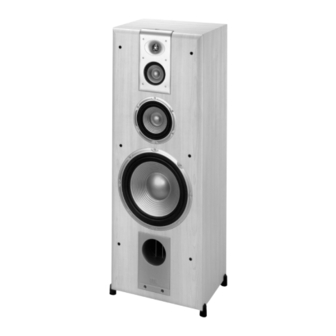
S412P MECHANICAL PARTS LIST (See following page) Cabinet S412P (Not for Sale) Grille 335417-002 Low Frequency Transducer 12” PolyPlas™ cone shielded 335151-001 DC Resistance 5.6 ohms ±10% Mid-Bass Transducer 6.5” PolyPlas™ cone shielded 335148-001 DC Resistance 4.8 ohms ±10% Mid Frequency Transducer 4”... -
Page 10: Cabinet Exploded View
EXPLODED VIEW... -
Page 11: Wiring/Passive Schematic Diagrams
WIRING DIAGRAM High Frequency Transducer 335663-001 YEL/BLK Crossover Terminal Network 335678-001 Mid-Frequency Transducer 335439-001 WHT/BLK GREEN/BLK Mid-Bass Amp Assembly Transducer 335679-001 335148-001 GREEN GREEN Low Frequency Transducer 335151-001 Power Cord S412P PASSIVE SCHEMATIC DIAGRAM 100uF 1.2 Ohm 100 V 2.6 mH 10 W Grn/Blk .205... -
Page 14: Integrated Circuit Drawings
Integrated Circuit Drawings TIP 41C 2SC 1815 U201,202 (TL074) QUAD OP-AMP TIP 42C 2SC 2235 AMP #3 AMP #4 2SA 1015 2SA 965 B C E 2N 5401 2N5551 AMP #1 AMP #2 3 Collector 3 Collector Base Base 1 Emitter 1 Emitter IC101 (4558D) Dual Op Amp Dual In-Line Package (top view) -
Page 15: Electrical Parts List
JBL S412P Amplifier PARTS LIST Part Number Description Q'ty Designator Resistors 11012100j52 resistor 10 ohms 1/2W,+/-5% 52mm 1 R139 11012182j52 resistor 1.8K 1/2W,+/-5% CF 52mm 1 R152 11012221j52 resistor 220 ohms,1/2W,+/-5% CF 52mm R160,163 11014101j26 resisor100 ohms 1/4W,+/-5% CF 1... - Page 16 Part Number Description Q'ty Designator 1302g472md00 disk capacitor 4700P 400V +/-20% UL C001 1302b221k503 disk capacitor 220P 50V +/-10% C131,201,202,211,221 1302f104m503 disk capacitor 0.1U 50V +/-20% C107 1302f104z503 disk capacitor 0.1U 50V +80/-20% 10 C118,124,126,132,133,134,135,223, 227,228 1303f102k503 disk capacitor 0.001U 50V +/-10% 2 C137,207 1303f473m503 disk capacitor 0.047U 50V +/-20% 1 C212...
- Page 17 Part Number Description Q'ty Designator R/P to RCA jack-1 06-t3105007 screw M3*10 R/P to R/C-8 06-t4165016 screw 4*16 1010S412P PCB ass'y PCB to Brkt-8 06-m30809 machine screw M3*8*P0.5 IC to H/S-2, PCB to H/S-2 06-t30804 screw 3*8 101AS412P AI Ass'y 1740rcb242v1 jack RCA RCB-242V-1 JK201 1751c02v01 connector 2pin 2.5mm pitch...
-
Page 18: Boards
+AC -AC SW202 Q206 C111 R241 R242 P101/A R236 D206 C218 J103 R230 Q204 Q116 Q123 R224 J110 C222 Q119 C132 R141 Q128 R223 R220 R222 R221 C216 C227 R217 C226 R173 R218 R246 Q110 R210 C228 J216 E C B C137 Q131 R162... -
Page 23: Packaging
PACKAGING Upper Foam 335667-001 Microfoam Owner's Manual 335419-001 Warranty Card 331993-001 Survey Card 331384-001 Corner Protectors 335692-001 (4) Outer Carton 335420-001 Lower Foam 335667-001...
Need help?
Do you have a question about the STUDIO Series and is the answer not in the manual?
Questions and answers