Sun Yeh Electrical OM Series Operation Manual
Quarter-turn electric valve actuators
Hide thumbs
Also See for OM Series:
- Operation manual (40 pages) ,
- Manual (3 pages) ,
- Operation manual (46 pages)
Table of Contents
Advertisement
Quick Links
Advertisement
Table of Contents

Related Manuals for Sun Yeh Electrical OM Series


Summary of Contents for Sun Yeh Electrical OM Series
- Page 1 SY01-C003G-EN...
-
Page 2: Table Of Contents
【OM Series】Quarter -Turn Electric Valve Actuator Contents General Information ..........................1 1.1 Safety Instructions ......................... 1 1.2 Installation Notices ........................1 1.3 Inspection, Storage, Transport....................... 2 Product Overview ..........................3 2.1 Features ............................3 Product Mechanical Data ........................4 3.1 Parts Identification ........................4 3.2 Technical Information ........................ -
Page 3: General Information
【OM Series】Quarter -Turn Electric Valve Actuator 1. General Information Failure to follow safety instructions may cause serious injury, equipment damage, or voided warranty. 1.1 Safety Instructions Installation, maintenance and repair works must be performed by trained personnel. The handling shall follow the safety and warning instruction contained in this manual. -
Page 4: Inspection, Storage, Transport
【OM Series】Quarter -Turn Electric Valve Actuator Actuator should be installed in an upright or horizontal position. Do not mount upside down or below a horizontal position. These units are not designed to operate in vacuum spaces or where an explosive atmosphere exists. -
Page 5: Product Overview
【OM Series】Quarter -Turn Electric Valve Actuator 2. Product Overview OM series quarter-turn electric actuators offer torque ranges from 35 Nm to 4,500 Nm (310 in-lb to 40,000 in-lb). These actuators come standard with a C3, NEMA Type 4X, 5 & IP67 enclosure for outdoor use. -
Page 6: Product Mechanical Data
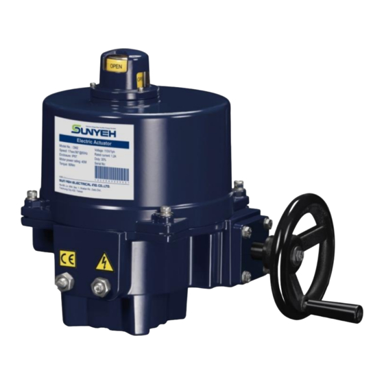
【OM Series】Quarter -Turn Electric Valve Actuator 3. Product Mechanical Data 3.1 Parts Identification Position Indicator Actuator Top Cover Label Top Cover Screw Handwheel Mechanical End Stops 3.2 Technical Information Torque Weight Motor Power Flange Type Model Manual Override in-lb ISO 5211... -
Page 7: Mounting Base Details
【OM Series】Quarter -Turn Electric Valve Actuator 3.3 Mounting Base Details 【OM-A, OM-AM, OM-F, OM-G, 【BM-2】 【OM-7 to OM-13】 OM-H, OM-J and OM-1 to OM-6】 Depth of Output Drive (B) Flange Type Output Drive (A) Key (C) Model ISO 5211 inch... -
Page 8: Sizing
3.5 Duty Cycle The standard duty cycle for OM series is 30% and 50% or 75% is for option. The duty cycle is the relationship between the running time and resting time. It is calculated as below:... -
Page 9: Mounting And Setup
【OM Series】Quarter -Turn Electric Valve Actuator 4. Mounting and Setup 4.1 Manual Device Installation (OM-2 to 13, OM-F, OM-G, OM-H and OM-J) Pass the screw through the handle and tighten the nut onto handwheel. Do not overtighten. Secure the handle to the wheel with the slotted screw and tighten the locknut all the way down to the wheel. -
Page 10: Valve Mounting Instructions
【OM Series】Quarter -Turn Electric Valve Actuator 4.2 Valve Mounting Instructions Make sure both the valve and actuator are in the same position before mounting, either fully-open or fully-closed. If not, use the manual override to correct this. Once mounted together, either directly or with a mounting kit, ensure that they are properly secured together and all fasteners are tightened. -
Page 11: Wiring Instructions
【OM Series】Quarter -Turn Electric Valve Actuator 4.3 Wiring Instructions Turn power off before making the electrical connection! Connect the ground wire to PE point placed on middle metal plate inside the electric actuator (a green screw) and wiring according to the wiring diagram inside the top cover. -
Page 12: Actuator Set-Up
【OM Series】Quarter -Turn Electric Valve Actuator 4.4 Actuator Set-up The power must be off during this procedure so as to avoid damage to the actuator. Do not make adjustments to the mechanical end stops when actuator is in motion. All steps below must be completed before normal operation. - Page 13 【OM Series】Quarter -Turn Electric Valve Actuator 4.4.2 Adjustment Steps Turn power off. b. Loosen the locknut and unwind both Open and Close Mechanical end stop screws for 7 turns. 【Open】 Mechanical End Stops 【Close】 When choosing modulating units or VR, loosen the M5 set screw on the sector gear or round gear.
- Page 14 【OM Series】Quarter -Turn Electric Valve Actuator OM-2 to OM-13, OM-F, OM-G and OM-H Rotate the cam TC1 counter-clockwise to contact the switch arm. Slowly rotate the cam TC1 counter-clockwise until a light click is heard. OM-J Rotate the cam TC1 clockwise to contact the switch arm.
- Page 15 【OM Series】Quarter -Turn Electric Valve Actuator OM-A and OM-AM Shaft Set Screw M5 TC2 “CLOSE” Clockwise: increase closing degree. Counter-clockwise: decrease closing degree. TC4 (Optional Item) TC1 “ OPEN” Clockwise: decrease opening degree. Counter-clockwise: increase opening degree. TC3 (Optional Item)
- Page 16 【OM Series】Quarter -Turn Electric Valve Actuator OM-2 to OM-13, OM-F, OM-G and OM-H Shaft Set Screw M3 TC2 “CLOSE” Clockwise: decrease closing degree. Counter-clockwise: increase closing degree. TC4 (Optional Item) TC1 “ OPEN” Clockwise: increase opening degree TC3 (Optional Item) Counter-clockwise: decrease opening degree.
- Page 17 【OM Series】Quarter -Turn Electric Valve Actuator Supply power to the fully-open position. Screw in the Open (left) Mechanical end stop screw until it bottoms out (refer to P.11 4.4.2), then turn back for 1/2, 3/4 or 1 turn based on the actuator model listed below.
-
Page 18: Torque Switch (Optional)
【OM Series】Quarter -Turn Electric Valve Actuator 5. Torque Switch (Optional) 5.1 Instructions The torque switch provides overload protection to prevent damage to the actuator due to torque overload. This option has been installed and calibrated before shipment from the factory, please do not adjust the torque limit setting value arbitrarily. -
Page 19: Modulating Control Board Adjustment
【OM Series】Quarter -Turn Electric Valve Actuator 6. Modulating Control Board Adjustment 6.1 Modulating Control Board (OM-1, OM-A & OM-AM) 6.1.1 Surface The layout is based on 110 / 220 V AC . 1 2 4 5 6 7 11 12 6.1.2... - Page 20 【OM Series】Quarter -Turn Electric Valve Actuator 6.1.3 Dip Switch Setting (SW1) The Dip Switch SW1 is a combination of 8 switches and equally divided in two rows. It is utilized to select signal type of input as well as output and fail positioning when the signal input fails.
- Page 21 【OM Series】Quarter -Turn Electric Valve Actuator Output signal setting (Switches 3 - 5) Output Signal State of Switch 4 - 20 mA 3 at OFF, 4 at ON, 5 at OFF 2 - 10V 3 at ON, 4 at OFF, 5 at ON Setting of fail position when input signal fails (Switches 6 - 8) The input signal type is set by switches 1 and 2.
- Page 22 【OM Series】Quarter -Turn Electric Valve Actuator The selection of the fail position while the input signal failed, please follow table below: Signal Failed Position State of Switch Fully-Open ( 90°) 7 at OFF, 8 at ON Fully-Closed ( 0° )
- Page 23 【OM Series】Quarter -Turn Electric Valve Actuator 6.1.4 Sensitivity Switch Setting (SW2) When the sensitivity setting is higher, the resolution of the input signal will be higher, and relatively the dead band will be smaller. Excessive high sensitivity setting may cause the actuator to keep hunting and could not run to the desired position which will lead to the thermostat inside the motor to trip because of overheating, and finally the actuator will shut down.
- Page 24 【OM Series】Quarter -Turn Electric Valve Actuator 6.1.5 Signal Setting for Open and Close Position These settings are set and calibrated at the factory. Be sure to reset the Signal Setting for Open and Close Position when recalibrating TC1 and TC2 for fully-open and fully-closed position or other signal types are required.
-
Page 25: Modulating Control Board (Om-2 ~ Om-13、Om-F、Om-G、Om-H)
【OM Series】Quarter -Turn Electric Valve Actuator 6.2 Modulating Control Board (OM-2 to OM-13,OM-F,OM-G & OM-H) 6.2.1 Surface The layout is based on 110 / 220 V AC voltage. 6.2.2 Programming Motor Motor Input Signal Σ Controller Driver Gear Box Output... - Page 26 【OM Series】Quarter -Turn Electric Valve Actuator 6.2.3 Dip Switch Setting (SW1) The Dip Switch SW1 is a combination of 8 switches and equally divided in two rows. It is utilized to select signal type of input as well as output and fail positioning when the signal input fails.
- Page 27 【OM Series】Quarter -Turn Electric Valve Actuator Output signal setting (Switches 3 - 5) Output signal can be fine-tuned by VR2. When resetting the Output Signal, be sure to fine-tune VR2 to match the setting either 2 - 10 V or 4 - 20 mA.
- Page 28 【OM Series】Quarter -Turn Electric Valve Actuator When S6 is set to Position Indicator Operating Output Input Signal (Fully-OpenFully-Closed) Position Signal Fully-Closed 1 V, 2 V, 4 mA LD1 ON 2 V, 4 mA Fully-Open 5 V, 10 V, 20 mA...
- Page 29 【OM Series】Quarter -Turn Electric Valve Actuator 6.2.4 Sensitivity Switch Setting (SW2) When the value of sensitivity (%) is lower, the resolution of the input signal will be higher, and relatively the dead band will be smaller. Excessive high resolution may...
- Page 30 【OM Series】Quarter -Turn Electric Valve Actuator 6.2.5 Signal Setting for Open and Close Position These settings are set and calibrated at the factory. Be sure to reset the Signal Setting for Open and Close Position when recalibrating TC1 and TC2 for fully-open and fully-closed position or other signal types are required.
- Page 31 【OM Series】Quarter -Turn Electric Valve Actuator 6.2.6 Troubleshooting of Modulating Controller (OM-2 to OM-13, OM-F, OM-G & OM-H) In case LD3 does not light or any of LD4 to LD9 lights when the actuator is motorized, please refer to steps below for basic troubleshooting.
- Page 32 【OM Series】Quarter -Turn Electric Valve Actuator Possible problems Solution Status of LEDs Signal output short circuits. a. Verify if the signal output with reversed polarity. The negative pole should be connected to terminal #11 and the positive Both DIP switch #3 and #4...
-
Page 33: Modulating Board With Modbus Function (Optional Item)
【OM Series】Quarter -Turn Electric Valve Actuator 6.3 Modulating Board with MODBUS Function (Optional Item) 6.3.1 Surface The layout is based on 110 / 220 V AC. MODE DOWN OM-A, OM-AM, OM-1 OM-2 to OM-13, OM-F, OM-G, OM-H OM-2 to OM-13, OM-F, OM-G, OM-H... - Page 34 【OM Series】Quarter -Turn Electric Valve Actuator 6.3.2 Dip Switch Setting (SW) The Dip Switch SW is a combination of 8 switches and equally divided in two rows. It is utilized to select signal type of input as well as output and fail positioning when the signal input fails.
- Page 35 【OM Series】Quarter -Turn Electric Valve Actuator To enable Analog Modulation: a. Input Signal Setting (switches 1 - 2) Input Signal State of Switch 4 - 20 mA 1 at ON, 2 at OFF 1 - 5 V 1 at OFF, 2 at OFF...
- Page 36 【OM Series】Quarter -Turn Electric Valve Actuator c. Setting of fail position when input signal fails (Switches 6 - 8) The input signal type is set by switches 1 and 2. And switch 6 is used to set the corresponding relationship between value of input signal and operation direction of actuator.
- Page 37 【OM Series】Quarter -Turn Electric Valve Actuator When S6 is set to The program defines 20 mA / 5 V / 10 V as a command for fully-open positioning. The line graph below shows the signal level and the corresponding position of the actuator.
- Page 38 【OM Series】Quarter -Turn Electric Valve Actuator 6.3.3 Sensitivity Switch Setting (SR1) OM-A, OM-AM, OM-1 to OM-13 and OM-H Factory setting: Select "MODBUS" control, the sensitivity is preset to 1. Select "analog signal" control, the sensitivity is preset to 7.
- Page 39 【OM Series】Quarter -Turn Electric Valve Actuator 6.3.5 Travel Setting Press “MODE” 5 times to get into Press and hold “SET” around 5 sec until “LOC” comes on to enter Auto setting mode. When the Auto setting is completed, “LOC” comes off and the actuator stops running.
- Page 40 【OM Series】Quarter -Turn Electric Valve Actuator Output signal setting for fully-closed position Use a multimeter to measure the output signal in accordance with the selected signal type. Press “MODE” several times until displays, then press “SET” once to enter signal setting mode.
- Page 41 【OM Series】Quarter -Turn Electric Valve Actuator 6.3.7 Time Delay Setting (OM-A, OM-AM, OM-1 ) Press “MODE” several times until displays, then press “SET” once to enter parameter setting mode. and Press and hold “SET” around 3 sec to enter setting mode.
- Page 42 【OM Series】Quarter -Turn Electric Valve Actuator OM-A, OM-AM, OM-1 ↑ ↑ Item Warning Message Item (9,8,7…0) Warning Message Solution Check if the input signal and (The latest data) dip switch settings are correct. Abnormal Input signal. No abnormal records. (The oldest data)
- Page 43 【OM Series】Quarter -Turn Electric Valve Actuator Example 1 If you want to check the latest data, press “MODE” several times until displays → Press “Set” once → The LED display will show the latest data b. If you want to check the eighth data, press “MODE” several times until displays →...
- Page 44 【OM Series】Quarter -Turn Electric Valve Actuator 6.3.9 MODBUS Setting MODBUS and modulating control cannot service at the same time. MODBUS : Set switches 1 - 2 at “ON” state and switches 3 - 8 at “OFF” state. Baud rate setting Press ”MODE”...
- Page 45 【OM Series】Quarter -Turn Electric Valve Actuator 6.3.10 MODBUS Parameter Address Parameter Address Setting range Function (Hexadecimal ) ( Hexadecimal ) Station setting for MODBUS 1 to 127 station Baud rate setting for MODBUS 4 to 5 Position setting (%) 0 to 64...
-
Page 46: Troubleshooting
【OM Series】Quarter -Turn Electric Valve Actuator 7. Troubleshooting Floating Control Motor can not operate or overheats. Possible problems Solution a. The limit switch for fully-closed does not a. Operate the actuator manually to trip. fully-closed position and confirm if the limit switch trips. - Page 47 【OM Series】Quarter -Turn Electric Valve Actuator The valve cannot operate either electrical operation or manual operation. Possible problems Solution a. The actuator was mounted to the valve a. Please refer to 4.2 (P.8) valve installation improperly. instructions. b. The set screw of the cam loosened and b.
- Page 48 【OM Series】Quarter -Turn Electric Valve Actuator Modulating Control The LED indicators (LD4 - LD9) flash. (OM-2 to OM-13, OM-F, OM-G & OM-H) Solution Please refer to 6.2.6 (P.29 - P.30). The LED indicators on the modulating board are normal, but the actuator cannot operate or can only operate in either the fully-open or fully-closed position.
-
Page 49: Warranty
【OM Series】Quarter -Turn Electric Valve Actuator 8. Warranty Sun Yeh Ele. Co. Ltd warrants that for a period of twelve months from the date of manufacture it will either repair or replace, at its option, any of its products which prove to be defective in material or workmanship.
Need help?
Do you have a question about the OM Series and is the answer not in the manual?
Questions and answers