Table of Contents
Advertisement
Quick Links
Advertisement
Table of Contents
Troubleshooting

Related Manuals for Sun Yeh Electrical S Series


Summary of Contents for Sun Yeh Electrical S Series
- Page 1 SY02-C001K-EN...
-
Page 2: Table Of Contents
【S Series】Spring Return Fail-safe Electric Valve Actuators Contents General Information ..........................1 Safety Instructions ........................1 Installation Notices ........................1 Inspection, Storage, Transport ....................2 Product Overview ..........................3 Features ............................3 Product Mechanical Data ........................3 Parts Identification ........................3 Technical Information ........................ -
Page 3: General Information
【S Series】Spring Return Fail-safe Electric Valve Actuators 1 General Information Failure to follow safety instructions may cause serious injury, equipment damage, or voided warranty. 1.1 Safety Instructions Installation, maintenance and repair works must be performed by trained personnel. ... -
Page 4: Inspection, Storage, Transport
【S Series】Spring Return Fail-safe Electric Valve Actuators Actuator should be installed in an upright or horizontal position. Do not mount upside down or below a horizontal position. These units are not designed to operate in vacuum spaces or where an explosive atmosphere exists. -
Page 5: Product Overview
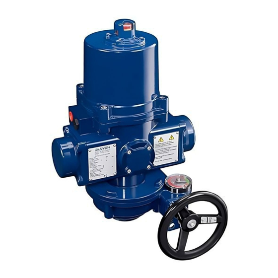
【S Series】Spring Return Fail-safe Electric Valve Actuators 2 Product Overview S series spring return fail-safe electric actuators offer torque ranges from 50 Nm to 360 Nm (445 in-lb to 3185 in-lb) and are designed for fail-safe positioning of valves or dampers upon loss of supply voltage, which include On / Off control, floating control and modulating control. -
Page 6: Technical Information
【S Series】Spring Return Fail-safe Electric Valve Actuators 3.2 Technical Information Weight Torque Motor Power Model Standard w / Manual Override in-lb S-500 S-1300 1150 S-2000 1770 131.5 S-2600 2300 133.5 S-3600 3185 3.3 Mounting Base Details Flange Type Output Drive (A) -
Page 7: Sizing
【S Series】Spring Return Fail-safe Electric Valve Actuators 3.4 Sizing For safety reasons, do not remove or inspect the SPRING STRUCTURE. Proper tools must be used, or serious injury will occur. The actuator shall be sized to ensure that its torque output meets the load requirements of valve. - Page 8 【S Series】Spring Return Fail-safe Electric Valve Actuators Ambient temperature and rated duty cycle : Standard Ambient Temperature: Model Controls Duty Cycle v.s. Ambient Temperature -30°C to +65°C (-22°F to +149°F) S-500 / S-1300 / On / Off Remarks: S-2000 / S-2600 / Floating 50% Duty Cycle: -30°C to +40°C (-22°F to +104°F)
-
Page 9: Mounting And Setup
【S Series】Spring Return Fail-safe Electric Valve Actuators 4 Mounting and Setup 4.1 Manual Device Installation Slide fixing screw through washers and handwheel and secure them to override shaft as shown in the figure below. Turn off power when installing handwheel. -
Page 10: Manual Device Indication Instruction
【S Series】Spring Return Fail-safe Electric Valve Actuators 4.2 Manual Device Indication Instruction Pointer Indication: If the actuator could not operate when supplying power, use the manual override to rotate the pointer to the green zone for normal operation. Zone: Actuator cannot operate normally when supplying power. -
Page 11: Valve Mounting Instructions
【S Series】Spring Return Fail-safe Electric Valve Actuators 4.3 Valve Mounting Instructions The spring return actuator is shipped in spring return position (spring released) with the configuration of spring clockwise and fully-closed when power outage unless specified. Refer to section 8 to ensure actuator selected meets the application. -
Page 12: Wiring Instructions
【S Series】Spring Return Fail-safe Electric Valve Actuators 4.4 Wiring Instructions Turn power off before making the electrical connection! Connect the ground wire to PE point placed on middle metal plate inside the electric actuator (a green screw). Each actuator is attached with a black water-proof plug and a temporary red dust-proof plug to conduit entries. -
Page 13: Actuator Set-Up
【S Series】Spring Return Fail-safe Electric Valve Actuators 4.5 Actuator Set-up If the actuator is equipped with a manual override, rotate the handwheel to return the actuator to its spring released position before the power is supplied. Securely tighten the conduit fittings to ensure the enclosure protection rating. - Page 14 【S Series】Spring Return Fail-safe Electric Valve Actuators 4.5.1 Adjustment procedure for spring-return actuator in the fail-closed position upon loss of supply voltage. Adjust FULLY-CLOSED (spring released) stop point as steps below: a. Turn power off and loosen the protection cover using a 5 mm hex key.
- Page 15 【S Series】Spring Return Fail-safe Electric Valve Actuators g. Tighten the cap screw of cam TC2. is utilized for sensing fully-closed stop point. Once the spring mechanism has been released when power outage, the actuator will not drive under power again until it has reached its fail stop position and is not triggering LS2.
- Page 16 【S Series】Spring Return Fail-safe Electric Valve Actuators Adjust FULLY-OPEN (spring compressed) stop point as steps below: Apply power to drive the actuator to its fully-open (spring compressed) position. If the open stop point is not aligned with the valve or damper properly, then it must be adjusted.
- Page 17 【S Series】Spring Return Fail-safe Electric Valve Actuators 4.5.2 Adjustment procedure for spring-return actuator in the fail-open position upon loss of supply voltage. Adjust FULLY-OPEN (spring released) stop point as steps below: a. Turn power off and loosen the protection cover using a 5 mm hex key..
- Page 18 【S Series】Spring Return Fail-safe Electric Valve Actuators g. Tighten the cap screw of cam TC2. is utilized for sensing fully-closed stop point. Once the spring mechanism has been released when power outage, the actuator will not drive under power again until it has reached its fail stop position and is not trigger LS2.
- Page 19 【S Series】Spring Return Fail-safe Electric Valve Actuators Adjust FULLY-CLOSED (spring compressed) stop point as steps below: a. Apply power to drive the actuator to its fully-closed (spring compressed) position. If the close stop point is not aligned with the valve or damper properly, then it must be adjusted.
- Page 20 【S Series】Spring Return Fail-safe Electric Valve Actuators 4.5.3 Modulating Control Actuators Potentiometer Setting For modulating actuators, after completing the calibration, turn the actuator to fully-closed or fully-open position (spring released) and follow the procedure below: Fail clockwise (CW) rotation Loosen M5 set screw.
-
Page 21: On-Off Control And Floating Control Board Adjustment
【S Series】Spring Return Fail-safe Electric Valve Actuators 5 On-Off Control and Floating Control Board Adjustment 5.1 On-Off Control Board Surface The layout is based on 110 / 220V. LED2 LED4 LED1 LED3 LS1 LS2 BRAKE Indicator Lamp Lamp No. -
Page 22: Troubleshooting Of On-Off Controller
【S Series】Spring Return Fail-safe Electric Valve Actuators 5.2 Troubleshooting of On-Off Controller In case LED1 to LED3 does not light or LED4 lights when the actuators are motorized, please refer to steps below for basic troubleshooting. Status of LEDs Possible problems... -
Page 23: Floating Control Board Surface
【S Series】Spring Return Fail-safe Electric Valve Actuators 5.3 Floating Control Board Surface The layout is based on 110 / 220 V. LED3 LED1 LED2 Indicator Lamp Lamp No. Status LED1 Spring Released LED2 Spring Compressed LED3 Power 2024.02... -
Page 24: Troubleshooting Of Floating Controller
【S Series】Spring Return Fail-safe Electric Valve Actuators 5.4 Troubleshooting of Floating Controller In case LED1 to LED3 does not light when the actuator is motorized, please refer to steps below for basic troubleshooting. Status of LEDs Possible problems Solution a. Abnormal control signal. -
Page 25: Modulating Control Board Adjustment
【S Series】Spring Return Fail-safe Electric Valve Actuators 6 Modulating Control Board Adjustment 6.1 Modulating Control Board Surface The layout is based on 110 / 220 V. LD1 - LD9 Dip Switch P4 Terminal 6.2 Programming Motor Σ Input Signal Controller... -
Page 26: Dip Switch Setting (Sw1)
【S Series】Spring Return Fail-safe Electric Valve Actuators 6.3 Dip Switch Setting (SW1) The Dip Switch SW1 is a combination of 8 switches and equally divided in two rows. It is utilized to select signal type of input as well as output and fail positioning when the input signal fails. - Page 27 【S Series】Spring Return Fail-safe Electric Valve Actuators c. Setting of fail position when input signal failed (Switches 6 - 8) The input signal type is set by switches 1 and 2. And switch 6 is used to set the corresponding relationship between value of input signal and operation direction of actuator.
-
Page 28: P4 Terminal
【S Series】Spring Return Fail-safe Electric Valve Actuators When S6 is set to The program defines 20 mA / 5 V / 10 V as a command for fully-open positioning. The line graph below shows the signal level and the corresponding position of the actuator. -
Page 29: Sensitivity Switch Setting (Sw2)
【S Series】Spring Return Fail-safe Electric Valve Actuators 6.5 Sensitivity Switch Setting (SW2) When the sensitivity setting is higher, the resolution of the input signal will be higher, and relatively the dead band will be smaller. Excessive high sensitivity setting may cause the... -
Page 30: Signal Settings For Open And Close Position
【S Series】Spring Return Fail-safe Electric Valve Actuators 6.6 Signal Settings for OPEN and CLOSE Position These settings are set and calibrated at the factory. Mostly, they do not need to be recalibrated. Please follow steps below to set when required. -
Page 31: Troubleshooting Of Modulating Controller
【S Series】Spring Return Fail-safe Electric Valve Actuators 6.7 Troubleshooting of modulating controller In case LD3 does not light or any of LD5 to LD9 lights when the actuator is motorized, please refer to steps below for basic troubleshooting. Please do the troubleshooting when LD5 to LD9 lights, and then restart the power to turn the lights off. - Page 32 【S Series】Spring Return Fail-safe Electric Valve Actuators Status of LEDs Possible problems Solution a. Duty cycle exceeded the rated. Please refer to 3.5 (P.5) and reduce the duty rating. LD8 goes on Motor over-current. b. Check the load. c. Check if the motor rotor is locked (For example: Valve is stuck by foreign objects).
-
Page 33: Troubleshooting
【S Series】Spring Return Fail-safe Electric Valve Actuators 7 Troubleshooting If the actuator selected with handwheel , after doing handwheel operation, be sure to use the handwheel to turn back to full-closed (spring released) position before input the power, it can be operating normally. - Page 34 【S Series】Spring Return Fail-safe Electric Valve Actuators The capacitor is faulty. Possible problems Solution The ambient temperature is too high or too The actuator should be installed within the low. rated ambient temperature range of -30 °C to +65 °C (-22 °F to + 149 °F).
-
Page 35: Actuator Options
【S Series】Spring Return Fail-safe Electric Valve Actuators 8 Actuator Options Fail clockwise (CW) rotation Fail counter-clockwise (CCW) rotation When energized, the driven valve When energized, the driven valve rotates rotates CCW (viewed from the top of CW (viewed from the top of the actuator). -
Page 36: Warranty
【S Series】Spring Return Fail-safe Electric Valve Actuators 9 Warranty Sun Yeh Ele. Co. Ltd. warrants that for a period of twelve months from the date of manufacture it will either repair or replace, at its option, any of its products which prove to be defective in material or workmanship.
Need help?
Do you have a question about the S Series and is the answer not in the manual?
Questions and answers