Advertisement
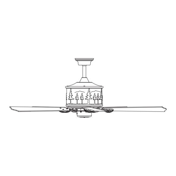
ORIGINAL VAXCEL CEILING FAN LIMITED LIFETIME WARRANTY*
*for full limited lifetime warranty details please see final page of these instructions.
Safety Instructions
READ ALL SAFETY INFORMATION AND INSTALLATION INSTRUCTIONS BEFORE YOU BEGIN TO
INSTALL THE FAN AND SAVE INSTRUCTIONS.
• All set screws of the fan must be checked and retightened where necessary before installation.
• To reduce the risk of personal injury, do not bend the blade brackets when installing the brackets,
balancing the blades or cleaning the fan. Do not insert foreign objects between rotating fan blades.
• Before changing the fan direction, turn off the fan and wait for the fan blades to stop completely.
• The safeguards provided by these safety instructions and by the separate installation instructions
are not meant to cover all possible conditions and situations that may occur. It must be understood
that common sense, caution and care are factors which can not be built into this product.
• These factors must be supplied by the person(s) installing, caring for and operating the fan.
WARNING
• TO AVOID RISK OF ELECTRIC SHOCK, BE SURE TO SHUT OFF POWER AT THE MAIN
FUSE OR CIRCUIT BREAKER BOX BEFORE INSTALLING OR SERVICING THIS
FIXTURE. TURNING OFF THE ELECTRICAL POWER BY USING THE LIGHT SWITCH
IS NOT SUFFICIENT TO PREVENT ELECTRICAL SHOCK.
• TO REDUCE THE RISK OF INJURY, INSTALL THE FAN SO THAT THE BLADES ARE
AT LEAST 7 FEET (2.1 METERS) ABOVE THE FLOOR AND AT LEAST 18 INCHES
(0.5 METERS) FROM THE TIP OF THE BLADES TO THE WALL.
• TO REDUCE THE RISK OF FIRE, ELECTRIC SHOCK, OR PERSONAL INJURY, MOUNT
TO OUTLET BOX MARKED "ACCEPTABLE FOR FAN SUPPORT" AND USE MOUNTING
SCREWS PROVIDED WITH THE OUTLET BOX.
• THE INSTALLATION HAS TO BE IN ACCORDANCE WITH THE NATIONAL ELECTRICAL
CODE, ANSI/NFPA 70-1999 AND LOCAL CODES. IF YOU ARE UNFAMILIAR WITH THE
METHODS OF INSTALLING ELECTRICAL WIRING, SEEK THE SERVICES OF A
QUALIFIED LICENSED ELECTRICIAN.
Model No.: F0011
PAGE: 1 / 10
230518
Advertisement
Table of Contents

Summary of Contents for Vaxcel Yosemite
- Page 1 ORIGINAL VAXCEL CEILING FAN LIMITED LIFETIME WARRANTY* *for full limited lifetime warranty details please see final page of these instructions. Model No.: F0011 Safety Instructions READ ALL SAFETY INFORMATION AND INSTALLATION INSTRUCTIONS BEFORE YOU BEGIN TO INSTALL THE FAN AND SAVE INSTRUCTIONS.
-
Page 2: Package Contents
Package Contents: Unpack your fan and check the contents. You should have the following items. 1.) Hanger Bracket 2.) Canopy 3.) Downrod Stand Cover 4.) Downrod Set (Included Hanger Ball, 6" Downrod, Hanger Pin & Lock Pin) 5.) Fan Fixture Set 6.) Blade Bracket (5PCS) 7.) Fan Blade (5PCS) 8.) Switch Box... - Page 3 Exploded View Detail Hanger Bracket Hanger Ball Canopy Downrod Downrod Stand Cover Hanger Pin Lock Pin Collar Housing Blade Bracket Blade Switch Box Dual Mount Drawing Downrod Mount Sloped Ceiling Mount ( Up to 23 degrees) PAGE: 3 / 10 230518...
-
Page 4: Installation Instructions
INSTALLATION INSTRUCTIONS IMPORTANT: BEFORE YOU BEGIN INSTALLING THE FAN, CAREFULLY READ ALL INFORMATION IN THE SEPARATE SHEET "SAFETY INSTRUCTIONS" AS WELL AS THE FOLLOWING "INSTALLATION INSTRUCTIONS". IF IN DOUBT, CONSULT A QUALIFIED ELECTRICIAN. SAVE ALL INSTRUCTIONS. NOTE: The fan weight is 21.1 lb (9.6 kg). Be sure the outlet box you are using is securely attached to the building structure and can support the full weight of the fan. - Page 5 Both the transmitter and receiver have a 4-key Transmitter unit code on each SUR Switch (Fig.8) and by default, all keys are pre-set to the "off" position. This means that the transmitter and receiver are already paired together. However, if you have multiple fans and remote controls and want to avoid interference between them, you can "pair"...
- Page 6 Fig.13 Fig.14 Fig.15 Switch Box Screw Plastic Insert Switch Box Blade Bracket Motor Screw Secure blade brackets to the motor with Assembly without fan light Connect the two terminals respectively motor screws and washers. Make sure the lead wire of fan light from the motor and the switch box.
- Page 7 Transmitter Screw Wall Bracket Install the transmitter wall bracket on the wall with two screws and place transmitter in it carefully. Fig.19 Replace the fan housing inner bulbs Fig.20 Screw 4-4W Type B11 E12 LED Bulbs Open the inner light plate of worse bulbs by screw driver. Take off the worse bulb and install the new one.
-
Page 8: Troubleshooting Guide
Troubleshooting Guide If you have difficulty operating your new ceiling fan, it may be the result of incorrect assembly, installation or wiring. If you experience any faults, please check this Troubleshooting Guide. If a problem cannot be remedied or you are experiencing difficulty in installation, please call our Customer Service Department. TROUBLE SUGGESTED REMEDY 1. - Page 9 DYNAMIC BLADE BALANCING KIT YARDSTICK BALANCING WEIGHT CENTERLINE MEASURING POINT COUNTER- CLOCKWISE PLASTIC CLIP PREFACE Your ceiling fan may sometimes have wobbling problems when operating due to irregularity in the blades or the blade brackets. Improper assembly in the mounting system may cause some additional problems. This balancing kit can be used to fix wobbling problems.
- Page 10 Vaxcel reserves the right to repair, replace or issue a credit for any properly installed product, provided it is returned per RMA instruction. This warranty is limited to the cost of the product only and does not extend to transportation, installation or replacement costs.


Need help?
Do you have a question about the Yosemite and is the answer not in the manual?
Questions and answers