Advertisement
Quick Links
User Manual
12 Ports L2 Managed Industrial-Grade Ethernet Switch
ST-IND0804MTS
Packing List
•
One Ethernet Switch
•
One User Manual
•
One Phoenix Terminal
•
Din-Rail Mounted Kits
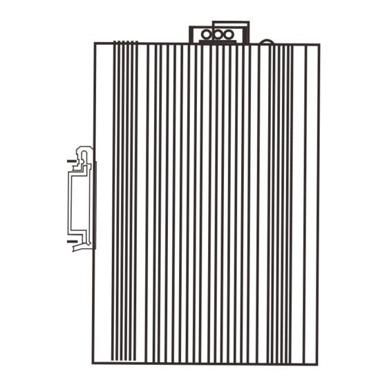
Side panel diagram
Alarm Output
Power input P2 terminal
Power input P1 terminal
Rear panel diagram
R
DC input
Console port
Recovery button (10s)
DIN-Rail
Product description
Front panel diagram
SYS
P2 Power Indicator light
9~12: 1000Mbps SFP Slots
status
Indicator light
ON
Switch power supply is normal
PWR
OFF
The switch is not powered on or the power supply is abnormal
The system is working fine
ON
SYS
The system does not start
OFF
ON
Port is connected
1~12
Flashing
Port is transmitting data
OFF
The port is not connected, or the connection is abnormal
Device installation
Installation Precautions
To avoid damage to the switch or personal injury caused by improper use, please observe the
following precautions.
For safety, please do not place the switch near water or damp places, and prevent water or
moisture from entering the switch case
• Please ensure that the working environment of the switch is clean. Excessive dust will cause
electrostatic adsorption, which will not only affect the life of the equipment, but also easily
cause Communication failure
• Please keep the ventilation holes of the switch unblocked, do not stack them
• Please ensure that the switch is working under a correct and stable voltage
• Before using the switch, be sure to reliably ground through the ground terminal on the rear
panel of the switch
• Before cleaning the switch, pull out the power plug of the switch. Please do not wipe the
switch with damp cloth, and do not use liquid cleaner Wash switch
• Do not open the case when the switch is working. Even when it is not powered.
Install equipment
Industrial switches support two installation methods, desktop installation and DIN rail
installation. The following will introduce the two installation methods respectively Specific steps.
Desktop installation
For devices without foot pads in the accessories, you can directly place the switch on a dry and
well-grounded workbench.
For the equipment with foot pads in the accessories, the specific installation process is as follows:
(1) Carefully turn the switch upside down. Clean the grooves on the bottom of the switch chassis
with a soft cloth, so that there is no oil or dust adsorption.
(2) Tear off the adhesive paper on the surface of the foot pad that comes with the machine, and
paste the foot pad into the groove on the bottom of the switch chassis.
(3) Carefully place the switch upright and place it on a clean, stable, and well-grounded workbench.
Rail installation
(1) Insert the top of the DIN rail into the notch under the rigid metal spring.
DC Indicator light
P1 Power Indicator light
1~8: 1000Mbps Rj45 Port
Description
Advertisement

Related Manuals for SEIAOTEK ST-IND0804MTS


Summary of Contents for SEIAOTEK ST-IND0804MTS
- Page 1 Front panel diagram DC Indicator light P2 Power Indicator light P1 Power Indicator light 1~8: 1000Mbps Rj45 Port User Manual 12 Ports L2 Managed Industrial-Grade Ethernet Switch ST-IND0804MTS 9~12: 1000Mbps SFP Slots Packing List status Indicator light Description • One Ethernet Switch Switch power supply is normal •...
- Page 2 1. Insert the negative/positive DC wire into the V-/V+ terminal of the terminal block. 2. In order to prevent the DC wires from loosening, please use a small flat blade screwdriver to tighten the wires in front of the terminals Clamp the screws. Metal spring 3.
Need help?
Do you have a question about the ST-IND0804MTS and is the answer not in the manual?
Questions and answers