Table of Contents
Advertisement
Quick Links
Advertisement
Table of Contents

Related Manuals for Epever MT52


Summary of Contents for Epever MT52
- Page 1 Remote Meter User Manual MT52...
-
Page 3: Table Of Contents
Contents Important Safety Instructions 1 General Information 1.1 Features 1.2 Main functions 1.3 Recommendations 2 Installation 3 Product Features 4 Operation 4.1 Buttons 4.2 Main menu 4.3 Real-time monitoring 4.4 Device information 4.5 Test operation 4.6 Control parameter 4.7 Load setting 4.8 Device parameter 4.9 Device password... - Page 4 4.10 Factory reset 4.11 Failure information 4.12 Meter parameter 5 Warranty 6 Technical Specifications Appendix Dimensions...
-
Page 5: Important Safety Instructions
This manual contains important safety, installation, and operating instructions for the remote meter. General safety information Please inspect the MT52 thoroughly after it is delivered. If any damage is seen, please notify the shipping company or our company immediately. A photo of the damage may be helpful. -
Page 6: General Information
1 General Information 1.1 Features The MT52 remote meter, using with the controllers designed with RS485 communication, can monitor the controller's real-time working status and program the parameters. Features: Easy to install and operate Real-time display of fault alarms ... -
Page 7: Recommendations
TRIRON, XTRA-N, XTRA-N G3 When the MT52 is connected with different devices, the configurable battery types are listed as the above table. For detailed battery types and setting method, refer to chapter 4.6 Control parameter. Note: Do not install the MT52 in a situation with strong electromagnetic... - Page 8 The MT52 comes standard with an RS485 communication cable (CC- RS485-RS485-200U). If it is connected to a controller with a not standard RJ45 interface, please purchase an appropriate communication cable in advance.
-
Page 9: Installation
2 Installation Frame mount dimensions (mm) Mechanical parameter Parameter Overall dimension 114mm x 114mm x 48.2mm Mounting dimension 84mm x 84mm Screw hole dimension Φ5... - Page 10 Step 2: Fix the frame with four ST4.2×3 self-tapping cross recessed pan head screws. Step 3: Use four M4×8 pan head screws to mount the MT52 panel on the frame. Step 4: Mount the four associated screw plugs into the screw holes.
- Page 11 Step 1: Locate and drill screw holes based on the installation size of the surface. Step 2: Use four M4×8 cross recessed pan head screws with M4 nuts to mount MT52 panel onto the surface. Step 3: Mount the four associated white screw plugs into the screw holes.
-
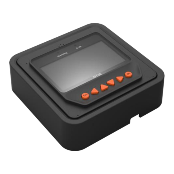
Page 12: Product Features
3 Product Features Front view... - Page 13 Module Function Failure indicator flashes when there is fault occurs. Failure indicator Refer to the user manual of the controller for detailed failure information. Communication Indicate the communication status between MT52 and the indicator connected controller. Display screen Man-machine interface.
- Page 14 Include four navigation buttons and two operational buttons. Buttons Refer to the 4.1 Buttons for specific directions. Connect with controller; used RJ45 interface communication and power supply. Note: Please use the communication plug, marked with "MT," to connect MT52. Monitoring screen...
- Page 15 Name LCD Display Instruction Night Day and night icons Note: The threshold voltage is 1V. When it goes higher than 1V, it is daytime. The icon is dynamically running Charge current icon when there is a charge current. battery capacity dynamically displayed.
- Page 16 Load On Load Off Load status icon Note: In the Manual Mode, press the "OK" button to switch on/off the load. Display the PV voltage and PV vol. and cur. values current values. Battery vol. and cur. Display the battery voltage and values current values.
-
Page 17: Operation
4 Operation 4.1 Buttons The buttons are respectively (from left to right) "ESC," "Left," "Up," "Down," "Right," and "OK". The operation is described in the diagram below: The default entry page is the browse mode. Press the button and input the correct password to enter the modification mode. -
Page 18: Main Menu
4.2 Main menu Enter the Main Menu by pressing buttons are respectively used to move the cursor to select the menu items, buttons are respectively used to enter or exit the corresponding pages of the menu items. 1. Monitoring 5. Load Set 9. - Page 20 Operational tips: Move between rows by pressing the buttons. Move along a row by pressing the buttons.
-
Page 21: Device Information
4.4 Device information The controllers' parameters are displayed below: Operational tips: buttons are respectively used to turn the browse page up and down. 4.5 Test operation Load switch test is conducted on the connection solar controller to check if the load output is normal. -
Page 22: Control Parameter
test. 4.6 Control parameter Browse, and modification operations are conducted over the control parame ters of the solar controller. Se e the scop e of parame ter modification in the control parameters table and the page of control parameters in the diagram below:... - Page 23 User define The battery type will display LiFePO4 15S/16S and Li(NiCoMn)O2 13S/14S only when the controller connected to the MT52 supports 48V system voltage. When modifying the battery type to "USE," the default voltage point is the corresponding voltage before the battery type is modified.
- Page 24 When the battery type is selected as the lithium battery (LiFePO4 and Li(NiCoMn)O2 series), the "Temp Comp. Coeff " and the "Rated Voltage" cannot be set. The software automatically enables the protection function of "Low temperature prohibits charge and discharge." 3) Voltage parameters Battery voltage parameters ...
- Page 25 Boost reconnect charging 13.2V 13.2V 13.2V 9~17V Voltage Low voltage reconnect voltage 12.6V 12.6V 12.6V 9~17V Under voltage 12.2V 12.2V 12.2V 9~17V warning reconnect voltage Under voltage warning voltage 12.0V 12.0V 12.0V 9~17V Low voltage disconnect voltage 11.1V 11.1V 11.1V 9~17V Discharging limit voltage 10.6V...
- Page 26 D. Under Voltage Warning Reconnect Voltage>Under Voltage Warning Voltage≥ Discharging Limit Voltage; E. Boost Reconnect Charging voltage >Low Voltage Reconnect Voltage. Lithium Battery voltage parameters Battery type Battery parameters ① User LFP4S LFP8S LFP15S LFP16S Over voltage disconnect 14.8V 29.6 V 55.5V 59.2V...
- Page 27 ① The battery parameters under the "User" battery type is 9~17V for LFP4S. They should x2 for LFP8S, and x4 for LFP15S/LFP16S. Battery LNCM type LNCM LNCM LNCM LNCM LNCM Battery ① User parameters Over voltage 12.8 V 25.6 V 29.8 V 55.4V 59.7V...
- Page 28 Under voltage 10.5 V 21.0 V 24.5 V 45.5V 49.0V 9~17V warning voltage voltage 9.3 V 18.6 V 21.7 V 40.3V 43.4V 9~17V disconnect voltage Discharging limit 9.3 V 18.6 V 21.7 V 40.3V 43.4V 9~17V voltage ① The battery parameters under the "User" battery type is 9~17V for LNCM3S. They should x2 for LNCM6S/LNCM7S, and x4 for LNCM13S/LNCM14S.
-
Page 29: Load Setting
(BMS)+0.2V 4.7 Load setting The page of load setting could be used to set the four load working modes of the connection solar controller (Manual, Light on/off, Light on + timer, Time control). √Manual Control Manual Control ◎Light On/off Default : ON ◎Light On+Timer ◎Time Control ◎Manual Control... - Page 30 controller manual. Manual control Mode Introductions The load is on if the battery capacity is enough and no abnormal conditions happen. The load is off all the time. 2. Light On/Off The load output is automatically turned on when the below situations occur at the same time: Light On voltage 1.
- Page 31 It means the confirmation time for the light signal. During this period, if the light signal voltage continues matching the Light Delay time On/Off voltage, the controller will perform corresponding actions (the time adjustment range: 0~99mins). 3. Light On+ timer Load working period after light Working time 1 control turns on the load...
- Page 32 4. Time control Control on/off time of the load Working time1 Working time through real-time clock mode. (T1) compulsory load working time Realize the dual timer function of the interval. Working time 2 is Working time2 load control through real-time clock optional.
-
Page 33: Device Parameter
4.8 Device parameter The solar controller's software version could be checked via the device parameter page. And device data like device ID, device LCD backlight time, and device clock could also be checked and modified. The device parameter page shows in the diagram below: Device Parameter Device Parameter... -
Page 34: Device Password
time. It indicates the Solar controller's internal clock. Month-Day-Year H: M: S 4.9 Device password The solar controller's password could be modified via the device password page. The device password is a 6-digit figure which is required before entering the modification mode of "Control parameter,"... -
Page 35: Failure Information
Factory Reset 4.11 Failure information The solar controller's failure information could be checked via the Failure information page (a maximum of 15 failure messages could be displayed). After the solar controller's failures are eliminated, the corresponding failure information will also be automatically eliminated. Failure Info 1.Over voltage 2.Over load... - Page 36 The PV input current exceeds the rated Input O. cur. current. The MOSFET of the reverse polarity RPP Short protection (RPP) is short-circuited. The MOSFET of the reverse polarity RPP Break protection (RPP) breaks. The MOSFET of the charge driver is short- Char.
-
Page 37: Meter Parameter
voltage warning (UVW) voltage value. The battery voltage is lower than the low Batt. LVD voltage disconnect (LVD) voltage value. Batt. Err The battery type is in error. 4.12 Meter parameter The meter's model, software, and hardware version could be checked via the meter parameter page. - Page 38 Parameters Default Range Remark Set the automatic switching interval for the Sw-Pages 0~120S real-time monitoring pages. Set the LCD backlight time. BKlight 0~999S Switch the display language between LangSel. Cn/En Chinese and English.
-
Page 39: Warranty
5 Warranty Maintenance Procedure Refer to the user manual or contact after-sales personnel to solve the faults before requiring maintenance. If it is confirmed that the maintenance needs to be carried out at the factory, send the product to our company by express delivery, prepay the shipping cost, and provide purchase invoice as the basis for warranty. -
Page 40: Technical Specifications
6 Technical Specifications Electrical Parameter Backlight ON<23mA Self-consumption Backlight OFF<15mA Mechanical Parameter Faceplate dimension 98mm × 98mm Frame dimension 114mm × 114mm Communication port RJ45 Communication cable (m) Standard: 2m, Longest: 50 m Simple package: 0.23 Kg Net weight Standard package: 0.32kg Environmental Parameter -20℃~+70℃... - Page 41 RJ45 pin definition: Pin No. Definition +5~12V Power input +5~12V Power input RS485-B RS485-B RS485-A RS485-A Data cable pin definitions...
-
Page 42: Appendix Dimensions
Appendix Dimensions Unit: mm Any changes without prior notice! Version number: V1.0... - Page 44 HUIZHOU EPEVER TECHNOLOGY CO., LTD. Tel: +86-752-3889706 E-mail: info@epever.com Website: www.epever.com...
Need help?
Do you have a question about the MT52 and is the answer not in the manual?
Questions and answers