Table of Contents
Advertisement
Quick Links
Advertisement
Table of Contents

Related Manuals for Epever MT75


Summary of Contents for Epever MT75
- Page 1 Remote Meter USER MANUAL MT75...
-
Page 3: Table Of Contents
Contents 1. Safety Instructions ..............1 2. Overview ................2 3. Appearance ................3 4. Accessories ................5 5. Installation Instructions ............6 6. Indicator Instruction .............. 8 7. Button Instruction..............9 8. LCD Display ................. 10 9. Error Codes ................12 10. -
Page 5: Safety Instructions
1. Safety Instructions Please keep this manual for future reference. Please read this manual and safety information carefully before using the product. Keep the product away from rain, exposure, severe dust, vibration, corrosion, and intense electromagnetic interference. Please avoid water, and other liquids enter into the product. -
Page 6: Overview
2. Overview MT75 is a new generation of remote meters that can monitor the EPEVER solar charge controller and inverter on one screen simultaneously. This product provides multiple solutions to fit different requirements from off-grid users. Features: Dual RJ45 communication ports ... -
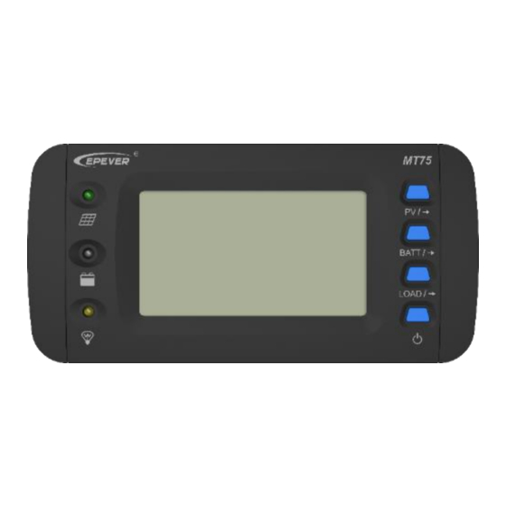
Page 7: Appearance
3. Appearance Decorative shell Battery parameter button ❶ ❽ PV indicator PV parameter button ❷ ❾ Battery indicator Base (optional) ❸ ❿ ① Load indicator Dry contact interface ❹ ⓫ RS485 port 1(RJ45) ❺ ⓬ Load ON/OFF button RS485 port 2(RJ45) ❻... - Page 8 ① Working Principle: Dry contact enable switch contact Dry contact Interface Dry contact rated value: 5A/30VDC; Max. value: 0.5A/60VDC Note: Turn the dry contact enable switch⓮ to ON only when the dry contact is used, and turn it OFF when not used to save the dry contact's loss.
-
Page 9: Accessories
Purpose Connect to the 3.81 pins remote 2P-3.81 plug 2 pcs control switch of inverter Connect the Included MT75 to the RJ45 2 pcs/CC-RS485- RS485 cable port of the RS485-200U controller or inverter Used for wall MT75 base 1 pcs... -
Page 10: Installation Instructions
(175x50mm), and erect the plastic expansion bolts. Step 2: Use four M5 self-tapping screws to fix the frame. Step 3: Remove the decorative shell. Step 4: Use two M4 pan head screws to mount the MT75 surface on the base. Step 5: Install the decorative shell. - Page 11 Step 2: Remove the decorative shell. Step 3: Use two M4 pan head screws to fix MT75. Step 4: Install the decorative shell.
-
Page 12: Indicator Instruction
6. Indicator Instruction Indicator Color Status Instruction Green ON solid PV is charging Green No PV charge Fast Green PV overvoltage flashing Green ON solid Battery normal Fast Green Battery overvoltage flashing Orange ON solid Battery under voltage ON solid Battery over-discharge Battery over temperature Slow... -
Page 13: Button Instruction
7. Button Instruction Button Operation Instruction Click Display PV parameters in cycle Click Display battery parameter in cycle Display load parameter in cycle Click Exit the fault page Press for 5S Check error code information Control the switch of solar controller Click ①... -
Page 14: Lcd Display
8. LCD Display LCD Display Symbol Definition Symbol Definition charging no charge Load ON Load OFF LCD Display Interface Item LCD Display Definition PV voltage PV current PV power ① Total PV generated power Battery voltage Battery... - Page 15 ① The "Total PV generated power" and "Total DC load usage" is the solar controller's parameter, which can be directly read and displayed by the MT75. ② The "Total AC load usage" is calculated based on the inverter's AC load power and displayed on the MT75.
-
Page 16: Error Codes
9. Error Codes Solar Controller Error Codes Indicator Color Status Code Fast Battery over Green flashing voltage Battery under —— Orange solid voltage Battery over- solid discharge Battery over temperature Slow Battery under flashing temperature Controller over temperature Fast Orange flashing System voltage... - Page 17 Inverter Error Codes Indicator Color Status Code Output short circuit Output overload Output voltage abnormal Busbar overvoltage Slow Green flashing Input overvoltage Input under- voltage Input over- current Inverter over temperature...
-
Page 18: Specifications
10. Specifications Model MT75 XTRA-N series/TRIRON series/ Tracer-AN series/Tracer-BN series Note: Required cables for the above Controller products are shipped with MT75. Compatible iTracer-AD series/iTracer-ND series products Note: Required cables for the above products need additional purchase. IPower series (1kw or above, suitable for... - Page 19 Working -20℃~+65℃ temperature Storage -20℃~+80℃ temperature 193×95×48mm(base) Dimension 193×95×23mm(no base) Mounting 175×50mm(base) size 176mm(no base) Mounting φ5mm(base) hole size φ4.3mm(no base) 0.29Kg(base) Net Weight 0.22Kg(no base)
-
Page 20: Dimension
11. Dimension Dimension without base Dimension with base... -
Page 21: Recommended Applications
PV, battery, AC load, DC load According to actual needs 3) Operations 1. Connect the RS485 ports of MT75 to the controller and inverter. 2. Set MT75's dry contact enable switch to OFF state. 3. Must set inverter switch to ON state. -
Page 22: Upgrade Application
4. MT75 load ON/OFF button directly controls the AC and DC load output. 12.2 Upgrade Application 1) Advantages MT75 monitors the operational status and error codes of the solar controller and inverter at the same time. The Load ON/OFF button controls the inverter start or stop, effectively reducing the inverter's loss and extending the system's lifetime. -
Page 23: Advanced Application
1. Connect the RS485 ports of MT75 to the controller and inverter. 2. Connect the MT75's dry contact interface to the inverter's external switch port. 3. Set MT75's dry contact enable switch to ON state. 4. Set inverter switch to OFF state. -
Page 24: Pro. Application
4. Must set inverter switch to ON state. 5. Set the parameters or monitor the operational status by the phone APP or PC software. 6. MT75 load ON/OFF button directly controls the AC and DC load output. 12.4 Pro. Application... - Page 25 1 pcs cable(Optional) Power cable 1 pcs PV, battery, AC load, According to actual needs DC load 3) Operations 1. Connect the main port of RS485-1M2S to controller and inverter. 2. Connect the slave port of RS485-1M2S to MT75 and...
- Page 26 5. Set inverter switch to OFF state. 6. Set the parameters or monitor the operational status by the phone APP or PC software. 7. MT75 load ON/OFF button controls inverter start or stop remotely. Any changes without prior notice! Version number:V2.0...
- Page 28 HUIZHOU EPEVER TECHNOLOGY CO., LTD. Beijing Tel: +86-10-82894896/82894112 Huizhou Tel: +86-752-3889706 E-mail: info@epsolarpv.com Website: www.epsolarpv.com www.epever.com...
Need help?
Do you have a question about the MT75 and is the answer not in the manual?
Questions and answers