Table of Contents
Advertisement
Advertisement
Table of Contents

Related Manuals for Epever MT Series


Summary of Contents for Epever MT Series
- Page 1 MT Series —— Remote Meter User Manual Models:MT11...
-
Page 3: Table Of Contents
Contents 1.Important Safety Instructions.............. 1 2.Overview .................... 2 3.Product classification ................. 3 4. Installation ..................4 4.1 Base of MT11 (Optional accessory) .......... 4 4.2 Wall installation steps ............... 5 4.3 Surface mounting steps ............7 5.Product Features ................8 5.1 Front View ................ -
Page 4: Important Safety Instructions
1.Important Safety Instructions Thank you for selecting the remote meter. General safety information Please contact our company or transportation if the product has been damaged. Please read this manual carefully before using the product and pay attention to the safety information. ... -
Page 5: Overview
2.Overview The MT series remote meter is an accessory which is compatible with the DuoRacer series controller. It can monitor the running data and working status of the controller via the remote meter. The remote meter can browse the controller’s parameters, set the battery typeand temperature unit, and clean the generated energy.It... -
Page 6: Product Classification
3.Product classification MT11(include the 1.5m communication cable) Remote meter MT11 1.5m communication cable (Model: CC-RS485-RS485-3.81-4P-150) Base of MT11 MT11 (include the 5m communication cable) Remote meter MT11 5m communication cable (Model: CC-RS485-RS485-3.81-4P-500) Base of MT11 MT11 (include the 10m communication cable) ... -
Page 7: Installation
4. Installation 4.1 Base of MT11 (Optional accessory) -
Page 8: Wall Installation Steps
Mechanical parameter Parameter Overalldimension 114 x 114 x 44.41mm Mountingdimension 88.6 x 88.6mm Φ5 Terminal 4.2 Wall installation steps Step1: Locate and drill screw holes based on the Frame Mounting dimension of the base,and erect the plastic expansion bolts. Step2: Use four PA4.2×32 self-tapping screws to fix the Frame. -
Page 10: Surface Mounting Steps
4.3 Surface mounting steps Step1: Locate and drill screw holes based on the installation size of the surface. Step2: Remove the decorative shell Step3:Use four M4×8 cross recessed pan head screws with M4 nuts to mount MT11 surface onto the panel. Step4:Install the decorative shell NOTE:Take full consideration of the plugging/unplugging space of the communication cable and the length of the cable during... -
Page 11: Product Features
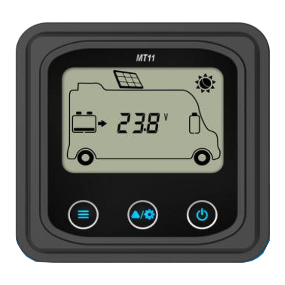
5.Product Features 5.1 Front View LCD display screen Man-machine interaction operation interface. Refer to the chapter 5 display and operation Buttons The meter buttons include two function buttons and one switch button. -
Page 12: Rear View
1.PV array parameters 2.Storage battery parameters Press the button 3.Browse the start battery parameters automatically ( Browse the PV array parameters Press the button Browse the Storage battery parameters Browse the start battery parameters Press the button Temperature unitsBattery type and hold on 5s Press the button The meter is powered ON... - Page 13 RS485communicationport It is used to connect the controller which Power the MT11. Communicationcable’s models CC-RS485-RS485-3.81-4P-150(Included) CC-RS485-RS485-3.81-4P-1000(Optional) CC-RS485-RS485-3.81-4P-2000(Optional) Pins definition Definition DC5V RS-485-B RS-485-A...
-
Page 14: Display And Operation
6.Display and operation 6.1LCD display Icon Instruction Icon Instruction BATT1 battery capacity BATT2battery capacity ① ① level 0~12% level 0~12% BATT1battery capacity BATT2battery capacity ① ① level 13%~35% level 13%~35% BATT1battery capacity BATT2battery capacity ① ① level 36%~61% level 36%~61% BATT1battery capacity BATT2battery capacity ①... -
Page 15: Auto Global View Mode
Night BATT1 charging icon Display the parameters BATT2charging icon of PV Display the parameters BATT1temperature of BATT1 parameters Display the parameters AES signal icon of BATT2 Setting icon Battery type icon Auto global view sign Minimum voltage icon Fault Icon Maximum voltage icon ①Battery power capacity is calculated by the linear relationship between the disconnect voltage of low voltage and float charging voltage. - Page 16 Echo Loop:PV voltage ——PV current ——PV power——Battery power——BATT1 voltage——BATT1 current——Max. BATT1 voltage——Min.BATT1 voltage——BATT1 temperature——BATT1 battery type——BATT2 voltage——BATT2 current——Max. BATT1 voltage——Min.BATT2 voltage——PV voltage...
-
Page 17: Temperature Units
6.3 Temperature units Operation: Step1: Press the button under the battery temperature interface. Step2: Press the button to select the temperature unit. Step3: Press the button to set successfully. 6.4 Clear the generated energy Press the button and hold on 5s to clear the generated energy. -
Page 18: Battery Type
6.5 Battery type 1)Operation: Step1: Press the button and hold 5s under the battery type interface. Step2: Press the button when the battery type interface is flashing. Step3: Press the button to confirm the battery type. 2) Battery type BATT112V Sealed BATT124V Sealed BATT112V Gel BATT124V Gel... - Page 19 CAUTION: Set the voltage of the “User” battery type via PC software only. 1) Lead-acid Battery Control Voltage Parameters The parameters are in the 12V system at 25 º C. Please double the values in the 24V system. Battery type Sealed Flooded User...
- Page 20 2) The following rules must be observed when modifying the value of the parameter in user battery type(factory default value is the same as sealed type): A. Over Voltage Disconnect Voltage > Charging Limit Voltage ≥ Equalize Charging Voltage ≥ Boost Charging Voltage ≥ Float Charging Voltage > Boost Reconnect Charging Voltage.
- Page 21 Voltage Low Voltage Reconnect Voltage 12.4V 10.5V 9~17V Under Voltage Warning Reconnect 11.0V 9~17V 12.5V Voltage Under Volt. Warning Voltage 10.5V 9~17V 12.0V Low Volt. Disconnect Voltage 9.3V 9~17V 11.0V Discharging LimitVoltage 10.8V 9.3V 9~17V The following rules must be observed when modifying the parameter values in User for the lithium battery.
-
Page 22: Fault Indication
WARNING: The required accuracy of BMS shall be at least 0.2V. If the deviation is higher than 0.2V, the manufacturer will assume no liability for any system malfunction caused by this. 6.6 Fault indication Fault Charge Fault Instruction indicator indicator Battery level BATT2 shows full, battery... -
Page 23: Technical Specifications
7.Technical Specifications Model MT11 Apply to model DRN series Self-consumption(Power on) 13mA/5Vdc Self-consumption(Power off) Communication way RS485 Communication port 3.81-4P CC-RS485-RS485-3.81-4P-150(1.5m) CC-RS485-RS485-3.81-4P-500(5m) RS485 cable CC-RS485-RS485-3.81-4P-1000(10m) Environment temperature -20℃~+70℃ Storage temperature range -20℃~+70℃ Enclosure IP20 Dimension 98.4×98.4mm Base cover dimension 114×114mm Weight 0.11kg Any changes without prior notice! - Page 24 BEIJING EPSOLAR TECHNOLOGY CO., LTD. Tel: +86-10-82894896 / 82894112 Fax: +86-10-82894882 E-mail:info@epsolarpv.com Website: www.epever.com...
Need help?
Do you have a question about the MT Series and is the answer not in the manual?
Questions and answers