Table of Contents
Advertisement
Quick Links
Advertisement
Table of Contents

Related Manuals for Epever MT91


Summary of Contents for Epever MT91
- Page 1 Remote Meter USER MANUAL MT91...
-
Page 3: Table Of Contents
Contents 1. Safety Instructions ................1 2. Overview ..................2 3. Appearance ..................3 4. Installation Instructions ..............6 5. Button Instruction................7 6. Real-time Interface ................. 8 7. Setting Interface ................9 8. Error Codes ..................13 9. Specifications ................. 14 10. -
Page 5: Safety Instructions
1. Safety Instructions Thanks for selecting the MT series; please read this manual carefully before using the product. Please keep this manual for future reference. When you receive the product, check whether there is any damage that occurred in transportation. -
Page 6: Overview
2. Overview MT91 is a new generation of remote meters specially designed for the EPEVER inverters. It displays the real-time parameter of the inverter on one screen. Supporting parameter configuration by the button operations, which makes the product suitable for different requirements. -
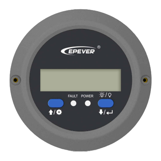
Page 7: Appearance
3. Appearance Screw hole Screw hole Down/OK button UP/Setting button Load switch« Fault indicator(red) Working indicator(blue) for 2 seconds to turn off the «In the real-time interface, long press load(default on); long-press it again for 2 seconds to turn on the load. - Page 8 Buzzer Remote terminal Inverter terminal Definition of the inverter terminal/remote terminal: B +5V B +5V...
- Page 9 RJ45-3.81-100U. The cable length can be customized according to customers' actual requirement.) Connect the MT91 with an auxiliary module Connect the "remote terminal" of the MT91 and the auxiliary modules such as the Bluetooth module/wireless module/BMS through an adapter cable.
-
Page 10: Installation Instructions
4. Installation Instructions Surface mounting installation is recommended. Step 1: Locate based on the installation size (91mm) and drill two screw holes (no smaller than 77x52mm). Step 2: Use two PWM3*10 screws to fix the remote meter. -
Page 11: Button Instruction
5. Button Instruction Button Operation Instruction Click Move up In the real-time interface (that is, the default interface after the device is powered on), press it for Press for 2s to enter the setting interface. In the setting interface, press it for 2s to enter the specific parameter configuration interface. -
Page 12: Real-Time Interface
6. Real-time Interface In the real-time interface(namely, the default interface after the device is powered on), please click to display the below parameters in a cycle. Battery voltage Load voltage Load current Load frequency Load power Note: means, the load being on status, means the load being off status. -
Page 13: Setting Interface
7. Setting Interface The parameter configuration process is as follows. Step1: In the real-time interface, press for 2s to enter the setting interface. Step2: Click to select the parameter to be configured. Step3: Press for 2s to enter the configuration interface of the specified parameter. - Page 14 Common parameters are shown in the following table: Parameters Default User define Display Output 220VAC 220VAC/ 230VAC voltage class ① 110VAc 110VAC/ 120VAC Output 50Hz 50Hz/60Hz ① frequency 30s/ 60s/100s(ON solid) backlight time Low voltage 12V: 10.8V 12V:10.5V~14.2V; step size:0.1V disconnect 24V: 21.6V 24V: 21V-30.2V;...
- Page 15 After configuring the parameters marked with , the inverter will restart ① ① automatically. It will resume work according to the new parameter value. NPower and IPower-Plus series support the modification of parameters ② marked with . Please refer to the following rules for the modification; ②...
- Page 16 Detail status is shown as the following when reaching the protection voltage point. Input voltage Status protection The output is switched OFF. The blue indicator fast flashes. Over voltage protection Buzzer beeps. LCD displays the The blue indicator is ON solid. Over voltage reconnect The output voltage is normal.
-
Page 17: Error Codes
8. Error Codes Error Working Fault Faults Buzzer code indicator indicator Inverter over temperature 5 beeps ON solid Heat sink over temperature Fast Input over 5 beeps flashing voltage (1Hz) Slowly Input low 5 beeps flashing voltage (1/4Hz) Fast Output short 5 beeps flashing circuit... -
Page 18: Specifications
9. Specifications Model MT91 Compatible products NPower/IPower-Plus/IPower Power supply 5VDC Power supply method Inverter communication port LCD visual angle 12' clock LCD backlight Installation method Surface mounting installation 14mA/5V(no backlight) Self-consumption 23mA/5V(backlight) Working temperature -20℃~+60℃ Storage temperature -35℃~+70℃ Dimension φ100mm X 19.4mm(Diameter X Height) Mounting dimension φ100mm X 50mm(Diameter X Height) -
Page 19: Dimension
10. Dimension Any changes without prior notice! Version number: V1.1... - Page 20 HUIZHOU EPEVER TECHNOLOGY CO., LTD. Beijing Tel: +86-10-82894896/82894112 Huizhou Tel: +86-752-3889706 E-mail: info@epsolarpv.com Website: www.epsolarpv.com www.epever.com...
Need help?
Do you have a question about the MT91 and is the answer not in the manual?
Questions and answers