Table of Contents
Advertisement
Quick Links
Advertisement
Table of Contents

Related Manuals for Epever MT50


Summary of Contents for Epever MT50
- Page 1 Remote Meter User Manual Model: MT50...
-
Page 3: Table Of Contents
Contents 1 Important Safety Instructions ..........1 2 General Information ............2 2.1 Features......................2 2.2 Main functions ....................2 2.3 Recommendations .................... 3 3 Installation ................4 4 Product Features ..............7 5 Operation ................12 5.1 Buttons......................12 5.2 Main menu ...................... - Page 4 5.9 Device password....................28 5.10 Factory reset ....................29 5.11 Failure information ..................29 5.12 Meter parameter ..................... 30 6 Technical Specifications ............32 Appendix Dimensions ............34...
-
Page 5: Important Safety Instructions
This manual contains important safety, installation, and operating instructions for the Remote Meter. General safety information Please inspect the MT50 thoroughly after it is delivered. If any damage is seen, please notify the shipping company or our company immediately. A photo of the damage may be helpful. ... -
Page 6: General Information
1 General Information 1.1 Features MT50 is a new generation of remote meters designed based on the latest controller communication protocol and voltage technical standards. The products have many excellent features: Automatically identify and display the relevant parameters of controllers;... -
Page 7: Recommendations
Applicable Models Interface Product series Battery type Communication type LS-B, GM-N, RJ45 VS-BN, Tracer-BN Battery RS485 ITracer-AD/ND 3.81-4P Tracer-AN, TRIRON, Battery+ Lithium RJ45 XTRA battery Note: Please do not install the MT50 in a situation with strong electromagnetic interference. -
Page 8: Installation
2 Installation Frame Mount Dimensions(mm) Mechanical parameter Parameter Overall dimension 114 x 114 x 48.2mm Mounting dimension 84 x 84mm Φ5 Terminal... - Page 9 Step 2: Use four ST4.2×32 self-tapping screws to fix the frame. Step 3: Use four M4×8 pan head screws to mount the MT50 surface on the frame. Step 4: Mount the four associated screw plugs into the screw holes.
- Page 10 Step 1: Locate and drill screw holes based on the installation size of the surface. Step 2: Use four M4×8 cross recessed pan head screws with M4 nuts to mount MT50 Surface onto the panel. Step 3: Mount the four associated white screw plugs into the screw holes.
-
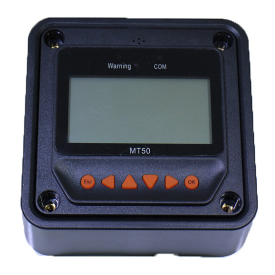
Page 11: Product Features
3 Product Features Front view... - Page 12 Rearview RJ45 interface Module Function Failure indicator flashes in case of failure of the Failure indicator connected devices. For failure information, please check the Controller Manual. Communication Indicate communication status when MT50 is connected...
- Page 13 See the specific directions in the Operational Manual. Connect with the controller; it is used for communication RJ45 interface and power supply. Note: Please use the communication plug, marked with "MT," to connect MT50. Monitoring screen...
- Page 14 Name LCD Display Instruction Night Day and night icons Note: The threshold voltage is 1V. When it goes higher than 1V, it is daytime. The icon is dynamically running Charge current icon if there is a charge current. battery capacity dynamically displayed.
- Page 15 Load On Load Off Load status icon Note: In the Manual Mode, pressing the "OK" button to switch on/off the load. Display the PV voltage and PV vol. and cur. values current values. Battery vol. and cur. Display the battery voltage and values current values.
-
Page 16: Operation
4 Operation 4.1 Buttons The buttons are respectively (from left to right) "ESC," "Left," "Up," "Down," "Right," and "OK "buttons. The operation is described in the schematic operation diagram below: The default entry page is the browse mode. Press the button and input the correct password to enter the modification mode. -
Page 17: Main Menu
confirm and cancel the modification of the control parameters. 4.2 Main menu Enter the Main Menu by pressing "Esc." The "Up" and "Down" buttons are respectively used to move the cursor to select the menu items, "OK," and "ESC" buttons are respectively used to enter or exit the corresponding pages of the menu items. -
Page 18: Real-Time Monitoring
4.3 Real-time monitoring There are 13 pages under real-time monitoring. Please check it as below: 17.5V 13.8V 13.8V 15.2A 5.2A 10.0A Jan-01-2013 02:34:33 DisCh. Energy Char. Energy Day: 0.00kwh Day: 0.00kwh Mon: 0.00kwh Mon: 0.00kwh Total: 0.00kwh Total: 0.00kwh Battery Battery Battery Vol:... - Page 19 Vol: 0.0V Sta.: DisConnect Cur: 0.0A Fault: No Power: 0.0W Char.: PWM/MPPT Controller Temp.: 25.0℃ Sta.: Normal Load Load Sta.: Vol: 0.0v Fault: Cur: 0.0A Power: 0.0W Load Mode Information Operational tips: Move between rows by pressing the "Up" or "Down" buttons. Move along a row by pressing the "Right"...
-
Page 20: Device Information
4.4 Device information The controllers' parameters are displayed below: Operational tips: buttons are respectively used to turn the browse page upward and downward. 4.5 Test operation Load switch test operation is conducted on the connection solar controller to see if the load output is normal. -
Page 21: Control Parameter
test operation. 4.6 Control parameter Browse, and modification operations are conducted over the control parameters of the solar controller. See the scope of parameter modification in the control parameters table and the page of control parameters in the diagram below: Batt. - Page 22 Li(NiCoMn)O2 (3S/6S/7S/13S/14S) battery User If the controller connected to the MT50 supports 48V system voltage, the battery type will display LiFePO4 15S/16S and Li(NiCoMn)O2 13S/14S. When switching the battery type to "USE," the default voltage point is the corresponding voltage before the battery type is modified.
- Page 23 Li(NiCoMn)O2 series), the "temperature compensation coefficient" and the "rated voltage" cannot be set. The software automatically enables the protection function of "Low temperature prohibits charge and discharge." 3) Voltage parameters Battery voltage parameters The below parameters are measured in the condition of 12V/25º C. Please double the values in the 24V system and multiplies the values by 4 in the 48V system.
- Page 24 Low voltage reconnect voltage 12.6V 12.6V 12.6V 9~17V Under voltage 12.2V 12.2V 12.2V 9~17V warning reconnect voltage Under voltage warning voltage 12.0V 12.0V 12.0V 9~17V Low voltage disconnect voltage 11.1V 11.1V 11.1V 9~17V Discharging limit voltage 10.6V 10.6V 10.6V 9~17V Equalize duration 120min 120min...
- Page 25 E. Boost Reconnect Charging voltage >Low Voltage Reconnect Voltage. Lithium Battery voltage parameters Battery type ① Battery parameters User LFP4S LFP8S LFP15S LFP16S Over voltage disconnect 14.8V 29.6 V 55.5V 59.2V 9~17V voltage Charging limit voltage 14.6 V 29.2 V 54.7V 58.4V 9~17V...
- Page 26 Battery LCNM type LCNM LCNM LCNM LCNM LCNM Battery ① User parameters Over voltage 12.8 V 25.6 V 29.8 V 55.4V 59.7V 9~17V disconnect voltage Charging limit 12.6 V 25.2 V 29.4 V 54.6V 58.8V 9~17V voltage Over voltage 12.5 V 25.0 V 29.1 V 54.1V...
- Page 27 voltage 9.3 V 18.6 V 21.7 V 40.3V 43.4V 9~17V disconnect voltage Discharging limit 9.3 V 18.6 V 21.7 V 40.3V 43.4V 9~17V voltage ① The battery parameters under the "User" battery type is 9~17V for LFP4S. They should x2 for LFP8S and x4 for LFP15S/LFP16S. ...
-
Page 28: Load Setting
Please refer to the user guide or contact the sales for the details of setting operations. 4.7 Load setting The page of load setting could be used to set the four load working modes of the connection solar controller (Manual, Light on/off, Light on + timer, Time control) √Manual Control Manual Control ◎Light On/off... - Page 29 Manual control Mode Introductions The load is on if the battery capacity is enough and no abnormal conditions happen. The load is off all the time. 2. Light On/Off The load output is automatically turned on when the bellows occur at the same time: Light On 1.
- Page 30 3. Light On+ timer Load working period after light Working time 1 control turns on the load (T1) Any working time is set as "0"; Load working period before light it means this time will stop Working time 2 control turns off the load working.
-
Page 31: Device Parameter
4. Time control Control on/off time of the load Working time1 Working time through real-time clock mode. (T1) compulsory load working time Realize the dual timer function of the interval. Working time 2 is Working time2 load control through real-time clock optional. -
Page 32: Device Password
Type Notes It indicates the Solar controller's software and hardware version numbers. It indicates the Solar controller's communication ID numbers. It indicates the Solar controller's LCD backlight Bklight time. It indicates the Solar controller's internal clock. Month-Day-Year H: M: S 4.9 Device password The solar controller's password could be modified via the device password page. -
Page 33: Factory Reset
4.10 Factory reset The solar charger controller's default parameters could be restored via the Factory reset page. Including the "Control parameter," "Load setting," "Charge mode," and "Device password" could all be restored to the factory defaults (the factory default password of the devices is "000000"). -
Page 34: Meter Parameter
The meter's model, software, and hardware version could be checked via the meter parameter page. And the two parameters (Switch pages, Backlight) could be browsed and modified as well. Meter Para. Meter Para. Taye: MT50 Sw-Pages:000S Ver: V1.00+V1.00 Bklight:020S AudiAlam: OFF... - Page 35 the language selection page: Parameters Default Range Remark The automatic switchover inverter for real- Sw-Pages 0~120S time monitoring page LCD backlight time BKlight 0~999S Switch the page display language between LangSel. Cn/En Chinese and English.
-
Page 36: Technical Specifications
5 Technical Specifications Electrical Parameter Backlight ON<23mA Self-consumption Backlight OFF<15mA Mechanical Parameter Faceplate dimensions 98×98 mm Frame dimensions 114×114 mm Connector type RJ45 Meter cable Standard: 2m, Max.: 50 m Meter weight Simple package: 0.23 Kg Standard package:0.32 Kg Environmental Parameter -20℃~+70℃... - Page 37 Definitions of interface pins Pin No. Definition Power+5~12V input Power+5~12V input RS485-B RS485-B RS485-A RS485-A Data cable pin definitions...
-
Page 38: Appendix Dimensions
Appendix Dimensions Unit (mm) Any changes without prior notice! Version number:V3.2... - Page 40 HUIZHOU EPEVER TECHNOLOGY CO., LTD. Beijing Tel: +86-10-82894896/82894112 Huizhou Tel: +86-752-3889706 E-mail: info@epever.com Website: www.epever.com...
Need help?
Do you have a question about the MT50 and is the answer not in the manual?
Questions and answers