Advertisement
Quick Links
ALLEN + ROTH and logo design are trademarks or
registered trademarks of LF, LLC. All rights reserved.
Serial Number
Questions, problems, missing parts? Before returning to your retailer, call our customer
service department at 866-439-9800, 8 a.m. - 8 p.m., EST, Monday - Sunday.
You may also contact us anytime at ascs@lowes.com.
SS23657
Purchase Date
1
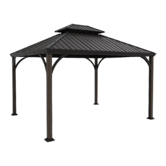
ITEM #5466083
Hardtop Gazebo
MODEL #GFM60901L
ATTACH YOUR RECEIPT HERE
Français p.
Advertisement

Related Manuals for Allen + Roth GFM60901L


Summary of Contents for Allen + Roth GFM60901L
- Page 1 ITEM #5466083 Hardtop Gazebo ALLEN + ROTH and logo design are trademarks or registered trademarks of LF, LLC. All rights reserved. MODEL #GFM60901L ATTACH YOUR RECEIPT HERE Français p. Serial Number Purchase Date Questions, problems, missing parts? Before returning to your retailer, call our customer service department at 866-439-9800, 8 a.m.
-
Page 2: Table Of Contents
TABLE OF CONTENTS Package Contents...........................3 Hardware Contents..........................6 Safety Information..........................6 Preparation............................8 Assembly or Installation Instructions ..................... 8 . Care and Maintenance........................22 Warranty............................22 PRODUCT SPECIFICATIONS SPECIFICATIONS 181.11 in W x 141.73 in D x 118.9 in H Black Finish Frame For outdoor use only. -
Page 3: Package Contents
PACKAGE CONTENTS... - Page 4 PACKAGE CONTENTS PART PART DESCRIPTION QUANTITY Post Leg Foot Plate Cover Foot Plate Short Side Left Beam Short Side Right Beam Long Side Left Beam Long Side Right Beam Beam Center Cover Corbel Beam Corner Cover Corner Rafter Connector Top Frame Connection 1 Top Frame Connectlon 2 Small-Top Tube 1 Small-Top Tube 2...
- Page 5 PACKAGE CONTENTS PART PART DESCRIPTION QUANTITY Small-Top Short Tube Small-Top Long Tube Hook 2nd Tier Short Side Roof Panel 2nd Tier Long Side Left Roof Panel 2nd Tier Long Side Right Roof Panel 2nd Tier Corner Cap 2nd Tier Top Cover Small-Top Netting 1 Small-Top Netting 2 Short Side Rafter Branch Assembly...
-
Page 6: Hardware Contents
HARDWARE CONTENTS (shown actual size) M6 x 10 mm M6 x 15 mm M6 x 25 mm M6 x 35 mm M6 x 45 mm Bolt Bolt Bolt Bolt Bolt Qty.164+8 Qty.16+1 Qty.28+2 Qty.18+1 Qty.12+2 AA II Φ6.5 x Φ6 x 1.0 mm Φ7 x Φ15 x 2.0 mm Nut Cap M6 x 55 mm... - Page 7 SAFETY INFORMATION DANGER This unit is heavy! Do not assemble this item alone. CAUTION Alwavs keep children under close supervision while they are using or around this product. Never leave children unattended. Do not climb on top of the gazebo. Falling off the gazebo can result in serious injury, possibly even death.
-
Page 8: Preparation
PREPARATION Before beginning assembly of product, make sure all parts are present. Compare parts with package contents list and hardware contents list. If any part is missing or damaged, do not attempt to assemble the product. Estimated Assembly Time: 3 Hours Note: Install all bolts by hand loosely threaded BEFORE fully tightening any bolts. - Page 9 ASSEMBLY INSTRUCTIONS 3. Install Long Side Left Beam (C3) into the Long Side Right Beam (C4), then connect it by using M6 x 10 mm Bolts (AA) and M6 X 15 mm Bolts (BB). Repeat x 2. Hardware Used M6 x 10 mm Bolt M6 x 15 mm Bolt...
- Page 10 ASSEMBLY INSTRUCTIONS 6. Place the assembled beam (C3) (C4) on Post C3 C4 Leg (A), secure it with M6 x 45 mm Bolts (EE) and Bolts (KK). Repeat x 4. Hardware Used M6 x 45 mm Bolt Bolt 7. IMPORTANT: Squaring the gazebo frame is a very important step to ensure easier assembly and proper fitment of parts.
- Page 11 ASSEMBLY INSTRUCTIONS 8. Secure the Corbel (E) to the beam (C1) C4 C3 C1 C2 (C2)(C3)(C4) by using M6 X 15 mm Bolts (BB). Repeat x 8. Hardware Used x 16 M6 x 15 mm Bolt 9. Secure the Beam Corner Cover (F) to the C4 C3 four corners by using M6 X 15 mm Bolts C1 C2...
- Page 12 ASSEMBLY INSTRUCTIONS 10. Install the Stud (LL) into Corner Rafter (G), secure the Connector (H) to the Corner Rafter (G) by using M6 X 15 mm Bolts (BB). Repeat x 4. Hardware Used M6 x 15 mm Bolt Stud 11. Place Small-Top Tube 1 (J1) and Small-Top Tube 2 (J2) between Top Frame Connection 1 (I1) and Top Frame Connectlon 2 (I2), secure by using M6 x 35 mm Bolts (DD), Φ6.5 x Φ6 x 1.0 mm...
- Page 13 ASSEMBLY INSTRUCTIONS 13. Secure 2nd Tier Corner Rafter (L) into Bottom Cover (K) by using M6 X 15 mm Bolts (BB). Secure Small-Top Short Tube (M1) and Small-Top Long Tube (M2) to 2nd Tier. Corner Rafter (L) by using M6 X 15 mm Bolts(BB). Repeat x 4.
- Page 14 ASSEMBLY INSTRUCTIONS 15. Lay 2nd Tier Short Side Roof Panel (O1), O2 O1 2nd Tier Long Side Left Roof Panel (O2) and 2nd Tier Long Side Right Roof Panel O1 O2 (O3) on the frame of step 14, secure by using M6 X 15 mm Bolts (BB).
- Page 15 ASSEMBLY INSTRUCTIONS Put the frame assembled in step16 on the frame in step12 and secure it using M6 X 15 mm Bolts (BB). Repeat x 4. Hardware Used M6 x 15 mm Bolt 18. Unfold Small-Top Netting 1 (R1) and Small-Top Netting 2 (R2).
- Page 16 ASSEMBLY INSTRUCTIONS 19. Secure Small-Top Netting 1 (R1) to the short side beam by using M6 X 15 mm Bolts (BB). Repeat x 2. Hardware Used M6 x 15 mm Bolt 20. Secure Small-Top Netting 2 (R2) to the long side beam by using M6 X 15 mm Bolts (BB).
- Page 17 ASSEMBLY INSTRUCTIONS 21. Secure the Short Side Rafter Branch Assembly (S1) and Long Side Rafter Branch Assembly (S2) to Small-Top Tube 1 BB S1 S1 S2 (J1) and Small-Top Tube 2 (J2) by using M6 X 15 mm Bolts (BB). Repeat x 4.
- Page 18 ASSEMBLY INSTRUCTIONS 23. Secure Long Side Left Roof Panel (T2) and Long Side Right Roof Panel (T3) to the long side beam by using M6 x 25 mm Bolts (CC) and Φ7 x Φ15 x 2.0 mm Washers (II). Repeat x 2. Hardware Used M6 x 25 mm Bolt...
- Page 19 ASSEMBLY INSTRUCTIONS 25. Install Left Small Roof Panel (Long &Short T4 T5 Side) (T6) and Right Small Roof Panel (Long & Short Side) (T7) into Left Middle Roof Panel (Long & Short Side) (T4) and Right Middle Roof Panel (Long & Short Side) (T5), secure with M6 X 15 mm Bolts (BB).
- Page 20 ASSEMBLY INSTRUCTIONS 27. Install Middle of Presser 1 (U2) on long roof panel, secure with M6 X 15 mm Bolts (BB). Repeat x 2. Hardware Used M6 x 15 mm Bolt C3 C4 C4 C3 C3 C4 28. Install Middle of Presser 2 (U3) on short roof panel, secure with M6 X 15 mm Bolts (BB).
- Page 21 ASSEMBLY INSTRUCTIONS 29. Secure Roof Corner Cap (V) to the roof corner by using 10 mm Nut with M6 Threads (GG), Φ7 x Φ15 x 2.0 mm Washers (II) and Nut Caps (JJ). Repeat x 4. Hardware Used 10 mm Nut with M6 Threads Φ7 x Φ15 x 2.0 mm Washer Nut Cap 30.
-
Page 22: Care And Maintenance
CARE AND MAINTENANCE Be careful to never allow water to build up in frames as this will cause corrosion and freeze damage in cold climates. Wash all frames with a solution of mild soap and water, Rinse with clean water and dry with a soft absorbent cloth towel. Frames can be treated with a liquid wax for maximum protection against UV rays and/or salty, damp air. - Page 23 WARRANTY OR IMPLIED INCLUDING THOSE OF RETAILING DEALERS.THIS EXCLUSIVE REMEDY IS LIMITED TO RECEIPT OF A CREDIT IN CONNECTION WITH THE REPAIR OR REPLACEMENT OF ANY PRODUCT OR COMPONENT DEEMED TO BE DEFECTIVE UNDER THE TERMS AND CONDITIONS AS STATED IN THIS WARRANTY. NEITHER THE PRODUCT MANUFACTURER NOR ITS AGENTS SHALL BE LIABLE IN ANY CASE FOR INCIDENTAL, INDIRECT, SPECIAL OR CONSEQUENTIAL DAMAGES RESULTING FROM THE USE OF THIS PRODUCT OR ARISING OUT OF ANY BREACH OF THIS WARRANTY OR NEGLIGENCE EVEN IF IT HAS BEEN ADVISED...
Need help?
Do you have a question about the GFM60901L and is the answer not in the manual?
Questions and answers