Table of Contents
Advertisement
Quick Links
Advertisement
Table of Contents

Related Manuals for TECH Sinum EHI-2


Summary of Contents for TECH Sinum EHI-2
-
Page 3: Table Of Contents
TABLE OF CONTENT Safety ................................5 Device description ............................6 How to install ..............................6 Controller operation .............................9 Operating principle ..........................9 Controller Functions – Main Menu ....................10 4.2.1 Central heating circuits ......................10 4.2.1.1 Operation modes ........................10 4.2.1.2 Central heating circuit 1,2 ...................... 10 4.2.1.3 Additional circuit 1/2...................... - Page 4 4.2.4 Settings ............................23 4.2.4.1 Language version ........................23 4.2.4.2 Screen settings ........................23 4.2.4.3 Lock ............................23 4.2.4.4 Time settings .......................... 23 4.2.4.5 Data settings .......................... 23 4.2.4.6 Software version ........................24 Protections ..............................24 Alarms ................................ 24 Technical data ............................25 Images and diagrams contained in the document serve illustrative purposes only.
-
Page 5: Safety
1. S AFETY Before operating the device, please read the following instructions carefully. Failure to observe instructions may cause damage to the device or even personal injury. Please store this manual for future reference. To avoid functional errors or accident, make sure that all persons operating the device are thoroughly familiarized with its operation and safety functions. -
Page 6: Device Description
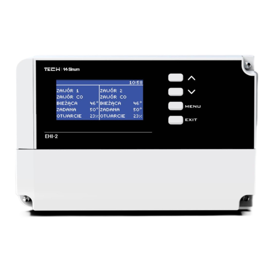
2. D EVICE DESCRIPTION The EHI-2 controller is a module for controlling the operation of two built-in valves and two additional valves. Through its sophisticated software, the controller can perform a number of functions: • Smooth 3- or 4-way mixing valve control •... - Page 7 Sample installation diagrams:...
- Page 8 It is possible to connect the EHI-2 controller to the Sinum Central device. To use this option, connect the EHI-2 module and the Sinum Central device directly to each other using an RS cable. The Sinum Central will automatically detect the EHI-2 controller and display it in the Tech RS devices tab in the Sinum Central device application.
-
Page 9: Controller Operation
4. C ONTROLLER OPERATION The device is operated via the use of four buttons. EXIT button - pressing it from the main screen position will bring up the screen view selection window showing: o panel view o valve 1, 2 o auxiliary pump o voltage-free contact o sensors. -
Page 10: Controller Functions - Main Menu
4.2 C – M ONTROLLER UNCTIONS 4.2.1 Central heating circuits The device allows independent control of two heating circuits according to the following operating modes: 4.2.1.1 Operation modes ➢ Mode - Boiler priority – enables operation of the DHW pump. After reaching the preset temperature in the boiler, the DHW pump switches off and the CH pump is switched on. - Page 11 Pump only Valve type CH valve Floor valve Return protection Cooling Opening time Room regulator Room regulator Control without room regulator Standard regulator of valve Room regulator function Room regulator temperature lower Closing Room regulator temperature lower Pump deactivation after heating Valve pump Pump operation modes Always ON...
-
Page 12: Pump Only (On / Off)
Temperature monitoring Opening direction Minimum opening Single stroke Proportional coefficient Calibration Valve weekly control Valve hysteresis Opening in CH calibration Valve closing Sensors selection* Own sensors* Main sensor* CH sensor* Own sensors* Main sensor* Security Boiler protection Return protection External sensor calibration* External temperature correction* Averaging time* Factory settings... -
Page 13: Maximum Floor Temperature
➢ Return protection - set so as to adjust the temperature at the return of our installation by way of a return sensor. Only return and boiler sensors are active when this setting is used, and the valve sensor is not connected to the controller. In this configuration, the valve protects the boiler's return from cold temperature as a priority, and if the boiler protection function is selected, it also protects the boiler from overheating. -
Page 14: Valve Pump
➢ Pump deactivation after heating (OFF/ON) – if enabled, the pump will switch off after receiving an “overheating” signal from the controller. If the option is switched off, the pump will operate independently of the regulator, and will use the readings from the settings on the valve, i.e. - Page 15 ➢ Opening direction - If, after connecting the valve to the controller, it turns out that it was supposed to be connected the other way round, the power cables need not be disconnected and switched over, instead, the opening direction in this parameter can be changed by selecting: LEFT or RIGHT. Note: This function is only available for built-in valves.
- Page 16 If the same change is wanted for neighboring hours, press the MENU button on the selected setting, and after the option appears at the bottom of the screen, select COPY and copy the setting to the subsequent or previous hour using the arrow buttons. Confirm the settings by pressing MENU. Example: Temperature - setting of Time...
-
Page 17: Sensor Selection
In this case, if the temperature set on the valve is 50°C Monday to Friday, from 04 to 07 hours, the temperature on the valve will increase by 5°C, or to 55°C; in the hours from 07 to 14 , it will decrease by 10°C, or to 40°C, while between 17 and 22 it will increase by 7... -
Page 18: External Sensor Calibration
way that when the temperature is too low, the valve closes until the shortened circuit of the boiler reaches the required temperature. The temperature below which the return protection is enabled, is selectable. NOTE Boiler Protection and Return Protection are not available in the Cooling mode. The Boiler Protection function is not available for the Floor Valve type. -
Page 19: Pump Type
4.2.3.3.1 Pump type ➢ OFF ➢ CH pump • Minimum temperature - temperature for switching ON the additional pump acting as a CH pump. Once this temperature is reached on the selected sensor, the pump will switch ON. • Hysteresis - auxiliary CH pump threshold temperature hysteresis. This is the difference between the threshold temperature and the shutdown temperature. - Page 20 ➢ Buffer pump The pump will operate on the basis of information from two temperature sensors. The device connected to the contact will switch on if on any sensor, the temperature drops below the set point (taking the hysteresis 1°C into account). Switching off will take place after reaching the set temperature on both sensors. •...
-
Page 21: Control Of Room Regulator
➢ Weekly control • Operation schedule - a weekly work schedule, as well as breaks in the operation of the pump for an entire week in cycles of 30 minutes duration can be set. Select Operation schedule, and then select the day of the week for which the programming of the operating plan is desired. -
Page 22: Need For Heating
4.2.3.4.1 Need for heating The device connected to the contact will work according to the reading from the selected sensor. The demand for heating can be realized according to the operation of the chosen type of contact (CH pump, DHW pump, additional heat source, buffer pump, etc.). •... -
Page 23: Test Screen
4.2.3.5 Test screen This parameter is intended only for service technicians with appropriate qualifications. The entry to this menu is secured by a code. This code is owned by the Tech Sterowniki II company. 4.2.4 Settings 4.2.4.1 Language version Option used to select the user's preferred software language. - Page 24 4.2.4.6 Software version This function enables users to obtain basic information about the driver software version. NOTE When contacting the Service Department of TECH STEROWNIKI, please provide the version number of the controller software. 5. P ROTECTIONS In order to ensure maximally safe and seamless operation, the controller has a number of safeguards. In the event of an alarm, an acoustic signal is activated and a message will appear on the display.
- Page 25 7. T ECHNICAL DATA Specification Unit Power supply voltage 230 +/-10% /50Hz Power consumption of the controller Ambient temperature 5÷50 Max. load on pump and valve outputs Nominal voltage-free contact load 230V AC / 0.5A (AC1)* 24V DC / 0.5A (DC1)** Sensor temp.
- Page 26 EU Declaration of Conformity The TECH STEROWNIKI II Sp. z o.o. company, with registered office in Wieprz, 34-122, at ulica Biała Droga 31, declares under sole responsibility that the EHI-2 manufactured by us meets the requirements of Directive 2014/35/EU of the European Parliament and of the Council of 26 February...
Need help?
Do you have a question about the Sinum EHI-2 and is the answer not in the manual?
Questions and answers